Monday, October 27, 2025

Tilt-Up Reinforced Concrete Arches

Tilt-up Reinforced Concrete Arches

A couple of years ago I began investigating masonry arches intended to compete with wooden roofing trusses. I thought that a masonry arch -made from manufactured concrete sections- would provide a better solution to providing a structure for roofing than conventional wooden trusses. The idea evolved as I began working on it and has resulted in a crude engineering model which proves the idea and serves as the basis for a prototype beyond the initial engineering model.


This first engineering model was made from sections designed to approximate units which could be rapidly mass-produced on a concrete block machine. They are 8 inches in height, the typical height of manufactured block. To produce these first samples affordably, relatively easily, and without too much fuss, I simply used 3-inch diameter PVC pipe as the molds. I cut these 8-inch sections with an angled or beveled top, each with a 60 wedge-shape at the top of the mold. Thus 15 sections would assemble into a 900 arched section, with a span of around 9 feet. This was to be my modestly scaled first model.


I wanted to include tensile reinforcement into these arch sections, so I included a hollow core through which rebar could be placed. To make this hollow core, I placed “pex” pipe sections, located in the center of 
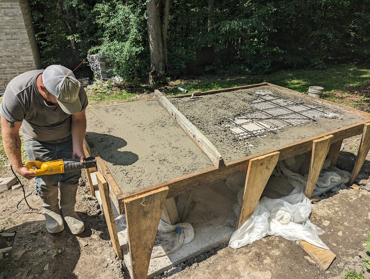
each PVC pipe section. These simple molds were then filled with concrete, one-third filled and compacted, then 2/3 filled and compacted, and filled to the top and compacted a final time, for consistent consolidation of the concrete within the molds. The cast concrete sections were removed from the molds the following day.


As crude as this method was, it allowed me to produce over 150 sections in a pretty short time.  I decided to assemble these using FRP (fiber reinforced polymer) rebar, which is lightweight and can flex and bend easily. This non-metallic rebar does not rust. I used a simple wooden form as a round section (900) to assemble these arch sections. I placed #3 basaltic FRP rebar (3/8-inch diameter) through the core holes of the arch sections and fastened the assembly to the wooden form and affixed a fill cup to both ends of the arch sections.


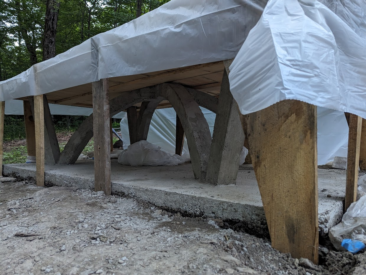
The assembly was then poured to fill the gap between the #3 rebar and the core hole, with a liquid grout, to cement the rebar to the concrete arch sections. The liquid grout filled this gap between the rebar and the concrete section with a gravity feed. It worked well, and I soon produced 7 arch sections. I realized that for this first test, I wanted a span slightly larger than the 9 feet provided by the 900 arch, so I added 3 additional arch sections to both ends of each arch. By turning each of these added arch section 1800 to one another, each arch section’s wedge-shape was oriented in a complementary fashion, thus adding a short, straight section to each arch: which approximates a catenary shape quite closely. The resulting arches could now span over 12 feet, which was close enough to what I desired for this initial test.


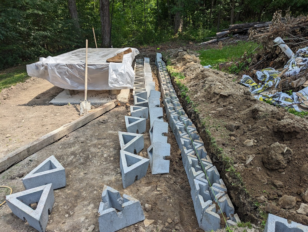
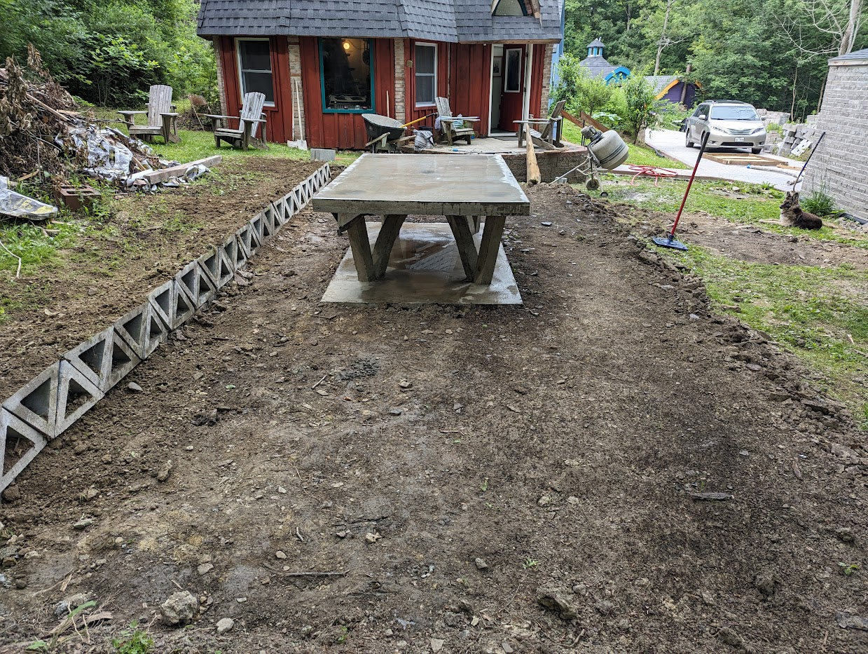
I decided to build a one-car garage, and to use these arch sections for the roof. The design I settled on was 21 ft. 4 inches in length, as described by 16 concrete block (CMUs). The garage is 14 feet wide, or 10.5 CMUs. The arches were arranged 32 inches O.C. (on center) in accordance with the modular coordination of CMUs.


Each arch had an extra length of FRP rebar sticking out from the concrete section, around 3 feet. This extra length of FRP rebar was used to bond the arch sections into the vertical walls of the garage, by inserting this rebar into the hollow core hole of the CMUs and grouting it into place. Each of these vertical core holes (32 in. O.C.) also had vertical rebar placed in them, so that continuous reinforcement was provided from the foundation up into the vertical block wall, into the arch, across the arch, and down into the opposite vertical wall and foundation.

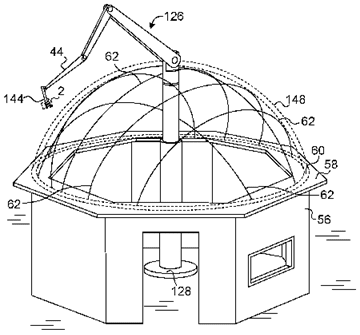
Once the vertical concrete block masonry walls of the garage were assembled, scaffolding was erected and used to help place the arches into position. One very useful feature of these reinforced masonry arches is that they can be tilted up easily into their vertical position. I was able to do this by myself by hand, with no special tools. For larger arches, any hoisting mechanism could be used for the tilt-up operation, such as a crane.


Much was learned from the assembly of this engineering model. It would be better to have the arch segments made with a rectangular cross section, as opposed to the round cross section used here (the round cross section was done simply for ease of molds made from 3-inch PVC pipe). By using a rectangular shape, the corners can readily be lined up, unlike the round sections, which tended to be less accurately aligned. The dimensions for the next design iteration will be rectangular: 3-inches by 4-inches cross section by 8-inches in length. This size will allow 32 of these arch sections to be made in a 3 at-a-time concrete block mold pallet (this size mold pallet will produce 3 standard 8-inch x 8-inch x 16-inch blocks per cycle). This provides for exceptional throughput, having 32 arch sections produced in around ten seconds. The 4-inch dimension of these arch sections will be aligned in the vertical direction of the assembled arch, to bear the load of the arch under gravity.

Another design consideration from this first experiment is to provide short grooves near the end surfaces of the arch segments. These grooves will house plastic screw anchors, so that a covering (wood, etc.) can be easily attached to the arches. These screw anchors will be cemented in place once the grout is poured into the core holes to cement the rebar to the concrete arch.

A building with a roof

AI-generated content may be incorrect.

Larger arches can be made from thicker arch segments. Multiple core holes can be provided, for greater reinforcement which utilizes more than one piece of rebar per arch. Larger arches will be heavier and more expensive. They can still be tilted up, using the proper equipment. On a larger scale, this system still provides practical, affordable, effective reinforced tilt-up masonry arches.

3D printed concrete can also be used to assemble reinforced tilt-up arches. 3D printing can be used by itself or in combination with concrete masonry units.

Tilt-up reinforced masonry arches can also be post-tensioned. This makes them stiffer and stronger.

A building under construction in the woods

AI-generated content may be incorrect.

A building with a ladder

AI-generated content may be incorrect.


Consideration of this design approach has led to a US patent application, which was recently filed. There is a patent pending currently. Here are some patent illustrations which help to show this idea.


The size of the market for wooden trusses in the US is estimated at between $10 – 13 billion. By providing an improved system for trusses, a significant opportunity is created. These reinforced concrete trusses can be rapidly assembled at a relatively low cost. By using either arch sections produced on a concrete block machine, or by 3DCP (3-dimensional concrete printing) and incorporating FRP rebar as reinforcement, arches can be produced affordably, quickly and with ease.

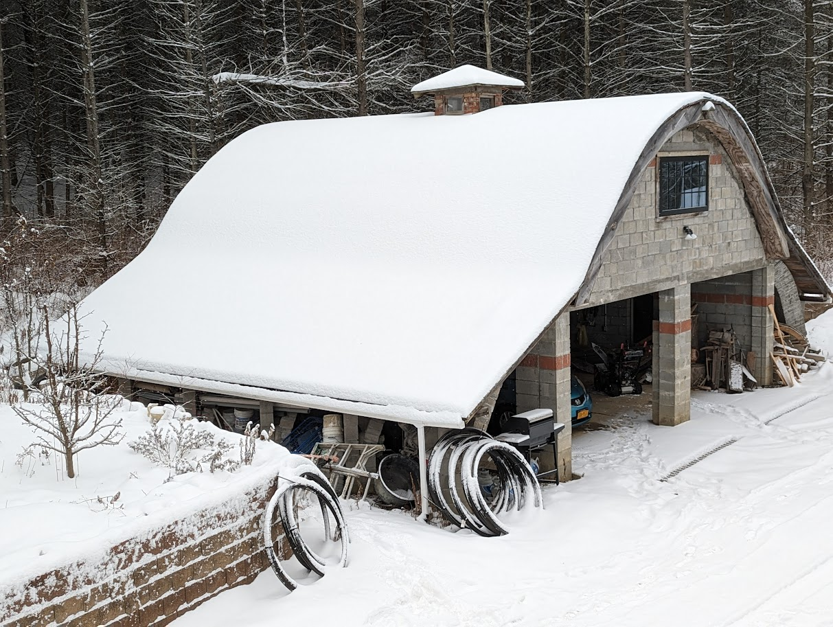
While the engineering model shown here has arches separated by spans, they may also be used assembled side-by-side, so that there is a continuous masonry arch roof. These arches may also be configured one on top of 
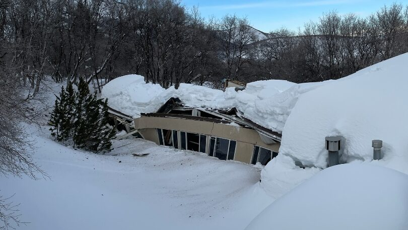
the other, for a thicker, stronger masonry arched roof. This design flexibility allows for roofs strong enough to withstand extreme weather events, including hurricanes, tornadoes, wildfires and more.

The benefits of reinforced concrete tilt-up arches include:

·       High strength

·       Affordable

·       Fire safe

·       Termite proof

·       Rot proof

·       Rust proof

·       Easy installation, via tilt-up

The continuing development of this roofing system promises to provide an improved method for making better buildings. There is huge potential here for economic benefit by providing these better buildings to the marketplace.

Thursday, February 20, 2025

Concrete Block Masonry Arched and Domed Roofs to Prevent Collapse from Snow Loads

Here in western New York State, this winter (2024-2025) has been pretty brutal. We had the coldest January in decades, and February is providing more of the same. This extremely cold weather is due to oscillations of the polar vortex, which dip down into lower latitudes and allow cold arctic air to occupy temperate zones to the South. These arctic oscillations are ironically due to global warming, as temperatures in the arctic have been record-breaking warmth. As I type this, it is currently 28 degrees F in Anchorage, Alaska; it is 8 degrees F here in western New York State.


One of the effects of this prolonged cold has been increased snowfall, due largely to lake effect snow, as the cold air passes over the Great Lakes it creates snow bands on the leeward, eastern edge of the Great Lakes. This increased snowfall has created a hazard to many buildings in its path: collapsing roofs.


A spate of collapsing roofs has occured over the past few days and weeks, as the weight of accumulating snow compromises roofs which are not designed to handle such heavy loads. These events include everything from modestly sized residential homes, to commercial buildings, to large manufacturing facilities. All of these types of structures have experienced roof collapse due to the large snow loads they've been subject to.


As climate change continues, these weather patterns are expected to continue as well. The polar vortex oscillations will continue into the future, and we can expect correspondingly brutal cold and increased snow, with a continuing possibility of collapsing roofs due to large snow loads. In my own experience, over the past ten years or so, the polar vortex oscillations are noticeably increasing. We experience prolonged periods of extreme cold here in western New York State as climate change progresses.


Personally, I do not worry about the possibility of a collapsing roof. This is due to the high compressive strength of concrete block masonry arched and domed roofs which are on top of all my masonry buildings. This structural arrangement is made stronger by additional weight. These roofs are squeezed together under the added weight of a snow load, which is how they are strongest. These structures do not suffer from the failures of wooden and metal trussed roofs. They are simply stronger under the conditions of high snowloads.


The benefits which concrete block masonry arched and domed roofs provide, which I've been describing for years on this blog, include: high strength, high thermal efficiency due to thermal mass benefits, fire safety, termite safe, low cost, ease of assembly, beautiful designs, and long life spans. It occurs to me that safety from a collapsing roof due to high snow loads should be added to this list of benefits for concrete block masonry arched and domed roofs.


Sunday, February 16, 2025

The Masonry Workforce and Automation

The masonry workforce faces shortages as it enters the future. Retiring masons are not being replaced by younger masons at an equal rate. The result is that the supply of skilled masonry workers does not meet the demand for this critically necessary skilled workforce to assemble masonry buildings and structures. This is not a sudden development; the industry has been aware of this troublesome trend for decades now. We need more masons.

Many commendable efforts are underway to recruit new masons into this important workforce, including efforts by the International Union of Bricklayers and Allied Craftworkers (BAC) and BAC’s educational and training organization, the International Masonry Institute (IMI). Additional recruitment efforts to help grow the skilled masonry workforce are underway by the Mason Contractors Association of America (MCAA) and several other regional and local masonry education and recruitment organizations.

Regardless of these excellent efforts to recruit new masons to the workforce, the supply of new masons simply does not meet the current demand for masons, nor is it expected to meet the growing demand in the future. What will be done to help supply the demand for masonry construction?

Part of the answer is to provide the masonry workforce with the tools, materials and techniques which will make human masons more efficient. This includes semi-automated methods and more fully automated assembly methods and equipment to help meet the demand for beautiful masonry buildings.

This includes lift-assist technologies, such as the MULE (Material Unit Left Enhancement) provided by Construction Robotics, to help masons work faster and more efficiently. It also includes exoskeletal equipment, provided by several companies, which are attached to the body of a human mason. It also includes much more fully automated systems, such as Fast Brick Robotics’ (FBR) “Hadrian X” robotic assembly system. The Hadrian X does not use mortar, but rather employs construction adhesive instead. At some point, this is no longer traditional masonry (without mortar) but becomes something else.

In my own experience, there has been resistance in the industry to adoption of semi-automated and fully automated masonry assembly methods and equipment. This is understandable! Masons don’t want to lose their jobs and be replaced by robots. The beauty of block requires the touch of a human mason.

Our company (Spherical Block, LLC) has been investigating new technologies, with a focus on semi-automated assembly tools and materials, for over a decade. I addressed this when I was invited to be keynote speaker at the North American Masonry Conference by The Masonry Society (TMS) in 2019, and was asked to talk about “Innovation in Masonry Today.”

Interest in these approaches has been growing slowly and steadily over the years. The path forward includes those processes and equipment which can help assemble masonry faster, more safely and more efficiently while providing the beauty of block to our buildings well into the future. This will require human masons, and the value that they add to our built environment. Using new tools, techniques and materials, masons will add even greater value to the world of construction. 


Wednesday, May 29, 2024

Stronger support for ocean front homes and buildings

Houses and buildings located along coastal areas are often susceptible to storm surges of ocean water, especially during hurricanes and extreme weather events. The damage done by this violent weather can be exacerbated by high tides.

These buildings are typically placed atop wooden posts and pilings. This configuration allows a storm surge to pass under the building, so that the building itself is not struck by the full force of a storm surge.  The forces of wind, water and wave are unrelenting for a building located along coastal plains, with a close proximity to the ocean. They are constantly under a barrage or attack by the forces of nature.


As Sea Level Rise (SLR) increases, the effects of wind water and wave are more pronounced on waterfront properties. Failure of the support systems currently used to keep these buildings above the plain of storm surge have become more common. It is expected that this situation will become more widespread and increasingly worse as SLR continues. Recently, failure of these support structures has taken place, especially on the Outer Banks of North Carolina. An article in today's USA Today (May 29, 2024) describes some of this damage.


There is a better way to keep a building located in a coastal plain elevated, other than the old, vulnerable method of using wooden posts. High-strength masonry arches, made with an appropriate concrete mix, and reinforced with basaltic FRP (Fiber Reinforced Polymer) rebar provide a very stable configuration. The high strength of concrete exceeds the strength of wood. The proper concrete mix, suitable for marine environments, can last much longer than a piece of wood. The arch configuration of this type of support structure is better able to withstand the lateral forces which are created by waves, wind and water; much stronger and more robust than vertically placed wooden posts.

This method can be rapidly assembled (done in just a few days), it is cost competitive with wooden posts, and it creates a visually striking pedestal for the building. The arches also provide easy access for parking, so the area underneath the building can be readily used.  Any number of platforms can be placed on top of the arch support structure, including reinforced flat concrete slabs, bubble decks, post-tensioned slabs, and so on.

Last summer, we made a concrete ping pong table (table tennis) out of concrete. The legs for the table were made as arches. using basaltic FRP rebar, cast within the concrete forms. This served as a scale model for a structure which could be used to support a building in a coastal plain, subject to storm surges, wave, wind and water. One can imagine this configuration made around 10 times larger; it would provide the perfect platform for building a house in a coastal flood plain, with parking underneath. 


The scalability of these designs is easy to grasp, if one looks at some of the larger arches made from our "Arch" block, which is assembled with 3 pieces of basaltic FRP rebar, as shown below (this shows a 30 ft. span). This configuration is very strong.  The straight sections, or legs, as shown on the corners of the ping pong table can be made from regular CMUs, where the hollow cores are reinforced with grouted FRP rebar. 


This method will allow houses to be built on very strong, affordable, long-lasting, elegant support systems which will allow them to survive further into the future in coastal areas prone to storm surges which are vulnerable to SLR. This will make coastal homes more resilient.


Wednesday, July 12, 2023

Making a concrete ping pong table

I recently completed making a concrete ping pong table. It came out pretty well, and I look forward to playing some ping pong!

Here are the basic steps I took to make and assemble the ping pong table.

First, I made wooden molds. There was a mold made for the table surface, a mold made for the central supporting arches, and four molds for legs which spring from the arches to the corners of the tabletop. Here are the molds, shown upside down.


Here is the arch section being made. There are 4 pieces of #3 rebar (3/8 inch diameter) in the arch form.  I used basaltic FRP rebar (fiber reinforced polymer).  All reinforcement was kindly donated by Nick Gencarelle of Smarter Building Systems. Nick is very knowledgeable and helpful.  We just used a bagged concrete mix, specified as having a strength of 4,000 psi after 28 days of curing.


Here are the four legs being made. Each leg also has 4 pieces of #3 FRP rebar.


Next, we set up a form for the base. The same form was used later for the tabletop. We placed #3 FRP rebar inside the form, at 10 inches on-center.  The arch form and leg forms were placed and cast directly in the concrete of the base.


After the base cured for a few days, we set up the mold for the tabletop. The mold was filled with basaltic FRP mesh reinforcement and also #3 FRP rebar, for tensile reinforcement.  The rebar was located so that it aligned with the legs underneath, for strength. The entire mold was greased with Crisco, used as a mold release agent. A sheet of plastic was placed on top of the wooden form, to help the concrete release from the mold.


The mold was then filled with concrete, with particular attention to place some concrete under the rebar, to help provide proper cover.  The concrete was then screeded (spread evenly with a straight piece of wood, moved back & forth as it is drawn across the form).  This surface was then floated, or smoothed out by hand.  The edges of the form were all vibrated. In this case, we did not have a proper concrete vibrator, so we used a "sawzall" reciprocating saw, which worked pretty well.


Properly floating the surface is important to get a nice, smooth, flat finish.  It is worth spending some time and doing this properly.


The form was then covered and allowed to cure for a full week. It helps to cover the concrete with plastic, so that water remains in the curing concrete to form hydration products.


After one full week, the wooden forms were removed. We also did some landscaping, to create a level playing surface on the ground around the table; this involved a retaining wall being placed also.  This work was simply done with a pick, shovel and rake. It took an afternoon. 


Now, it just needs a net! I will also use a sealant to help protect the concrete from the weather, something like Thompson's Water Seal.  This will also make a great picnic table. I expect it should last a long time. We will also plant some grass on the fresh dirt.

This basic concept could be made much larger, to provide an elevated platform to build homes on. We could use my company's masonry arch system to accomplish this, easily and quite affordably.  This would be appropriate for coastal areas which are prone to storm surges and flooding from hurricanes and severe weather. It is stronger than the wooden posts currently used to elevate homes above a storm-surge plain, and will not rust or rot, like wood. It is also more elegant and looks much better than those wooden posts.

This table cost about $150 in concrete.  The rebar is also inexpensive. If anyone wants a concrete ping pong table and would like to borrow my molds, you are welcome to.  Just let me know.

This thing should be fun, I look forward to using it!