Showing posts with label arches. Show all posts

Monday, October 27, 2025

Prefabricated Reinforced Concrete Arches

Prefabricated Reinforced Concrete Arches

A couple of years ago I began investigating masonry arches intended to compete with wooden roofing trusses. I thought that a masonry arch -made from manufactured concrete sections- would provide a better solution to providing a structure for roofing than conventional wooden trusses. The idea evolved as I began working on it and has resulted in a crude engineering model which proves the idea and serves as the basis for a prototype beyond the initial engineering model.


This first engineering model was made from sections designed to approximate units which could be rapidly mass-produced on a concrete block machine. They are 8 inches in height, the typical height of manufactured block. To produce these first samples affordably, relatively easily, and without too much fuss, I simply used 3-inch diameter PVC pipe as the molds. I cut these 8-inch sections with an angled or beveled top, each with a 60 wedge-shape at the top of the mold. Thus 15 sections would assemble into a 900 arched section, with a span of around 9 feet. This was to be my modestly scaled first model.


I wanted to include tensile reinforcement into these arch sections, so I included a hollow core through which rebar could be placed. To make this hollow core, I placed “pex” pipe sections, located in the center of each PVC pipe section. These simple molds were then filled with concrete, one-third filled and compacted, then 2/3 filled and compacted, and filled to the top and compacted a final time, for consistent consolidation of the concrete within the molds. The cast concrete sections were removed from the molds the following day.


As crude as this method was, it allowed me to produce over 150 sections in a pretty short time.  I decided to assemble these using FRP (fiber reinforced polymer) rebar, which is lightweight and can flex and bend easily. This non-metallic rebar does not rust. I used a simple wooden form as a round section (900) to assemble these arch sections. I placed #3 basaltic FRP rebar (3/8-inch diameter) through the core holes of the arch sections and fastened the assembly to the wooden form and affixed a fill cup to both ends of the arch sections.


The assembly was then poured to fill the gap between the #3 rebar and the core hole, with a liquid grout, to cement the rebar to the concrete arch sections. The liquid grout filled this gap between the rebar and the concrete section with a gravity feed. It worked well, and I soon produced 7 arch sections. I realized that for this first test, I wanted a span slightly larger than the 9 feet provided by the 900 arch, so I added 3 additional arch sections to both ends of each arch. By turning each of these added arch section 1800 to one another, each arch section’s wedge-shape was oriented in a complementary fashion, thus adding a short, straight section to each arch: which approximates a catenary shape quite closely. The resulting arches could now span over 12 feet, which was close enough to what I desired for this initial test.


I decided to build a one-car garage, and to use these arch sections for the roof. The design I settled on was 21 ft. 4 inches in length, as described by 16 concrete block (CMUs). The garage is 14 feet wide, or 10.5 CMUs. The arches were arranged 32 inches O.C. (on center) in accordance with the modular coordination of CMUs.


Each arch had an extra length of FRP rebar sticking out from the concrete section, around 3 feet. This extra length of FRP rebar was used to bond the arch sections into the vertical walls of the garage, by inserting this rebar into the hollow core hole of the CMUs and grouting it into place. Each of these vertical core holes (32 in. O.C.) also had vertical rebar placed in them, so that continuous reinforcement was provided from the foundation up into the vertical block wall, into the arch, across the arch, and down into the opposite vertical wall and foundation.

Once the vertical concrete block masonry walls of the garage were assembled, scaffolding was erected and used to help place the arches into position. One very useful feature of these reinforced masonry arches is that they can be tilted up easily into their vertical position. I was able to do this by myself by hand, with no special tools. For larger arches, any hoisting mechanism could be used for the tilt-up operation, such as a crane.


Much was learned from the assembly of this engineering model. It would be better to have the arch segments made with a rectangular cross section, as opposed to the round cross section used here (the round cross section was done simply for ease of molds made from 3-inch PVC pipe). By using a rectangular shape, the corners can readily be lined up, unlike the round sections, which tended to be less accurately aligned. The dimensions for the next design iteration will be rectangular: 3-inches by 4-inches cross section by 8-inches in length. This size will allow 32 of these arch sections to be made in a 3 at-a-time concrete block mold pallet (this size mold pallet will produce 3 standard 8-inch x 8-inch x 16-inch blocks per cycle). This provides for exceptional throughput, having 32 arch sections produced in around ten seconds. The 4-inch dimension of these arch sections will be aligned in the vertical direction of the assembled arch, to bear the load of the arch under gravity.

Another design consideration from this first experiment is to provide short grooves near the end surfaces of the arch segments. These grooves will house plastic screw anchors, so that a covering (wood, etc.) can be easily attached to the arches. These screw anchors will be cemented in place once the grout is poured into the core holes to cement the rebar to the concrete arch.

A building with a roof

AI-generated content may be incorrect.

Larger arches can be made from thicker arch segments. Multiple core holes can be provided, for greater reinforcement which utilizes more than one piece of rebar per arch. Larger arches will be heavier and more expensive. They can still be tilted up, using the proper equipment. On a larger scale, this system still provides practical, affordable, effective reinforced tilt-up masonry arches.

3D printed concrete can also be used to assemble reinforced tilt-up arches. 3D printing can be used by itself or in combination with concrete masonry units.

Tilt-up reinforced masonry arches can also be post-tensioned. This makes them stiffer and stronger.

A building under construction in the woods

AI-generated content may be incorrect.

A building with a ladder

AI-generated content may be incorrect.


Consideration of this design approach has led to a US patent application, which was recently filed. There is a patent pending currently. Here are some patent illustrations which help to show this idea.


The size of the market for wooden trusses in the US is estimated at between $10 – 13 billion. By providing an improved system for trusses, a significant opportunity is created. These reinforced concrete trusses can be rapidly assembled at a relatively low cost. By using either arch sections produced on a concrete block machine, or by 3DCP (3-dimensional concrete printing) and incorporating FRP rebar as reinforcement, arches can be produced affordably, quickly and with ease.

While the engineering model shown here has arches separated by spans, they may also be used assembled side-by-side, so that there is a continuous masonry arch roof. These arches may also be configured one on top of the other, for a thicker, stronger masonry arched roof. This design flexibility allows for roofs strong enough to withstand extreme weather events, including hurricanes, tornadoes, wildfires and more.

The benefits of reinforced concrete tilt-up arches include:

·       High strength

·       Affordable

·       Fire safe

·       Termite proof

·       Rot proof

·       Rust proof

·       Easy installation, via tilt-up

The continuing development of this roofing system promises to provide an improved method for making better buildings. There is huge potential here for economic benefit by providing these better buildings to the marketplace.


Wednesday, July 12, 2023

Making a concrete ping pong table

I recently completed making a concrete ping pong table. It came out pretty well, and I look forward to playing some ping pong!

Here are the basic steps I took to make and assemble the ping pong table.

First, I made wooden molds. There was a mold made for the table surface, a mold made for the central supporting arches, and four molds for legs which spring from the arches to the corners of the tabletop. Here are the molds, shown upside down.


Here is the arch section being made. There are 4 pieces of #3 rebar (3/8 inch diameter) in the arch form.  I used basaltic FRP rebar (fiber reinforced polymer).  All reinforcement was kindly donated by Nick Gencarelle of Smarter Building Systems. Nick is very knowledgeable and helpful.  We just used a bagged concrete mix, specified as having a strength of 4,000 psi after 28 days of curing.


Here are the four legs being made. Each leg also has 4 pieces of #3 FRP rebar.


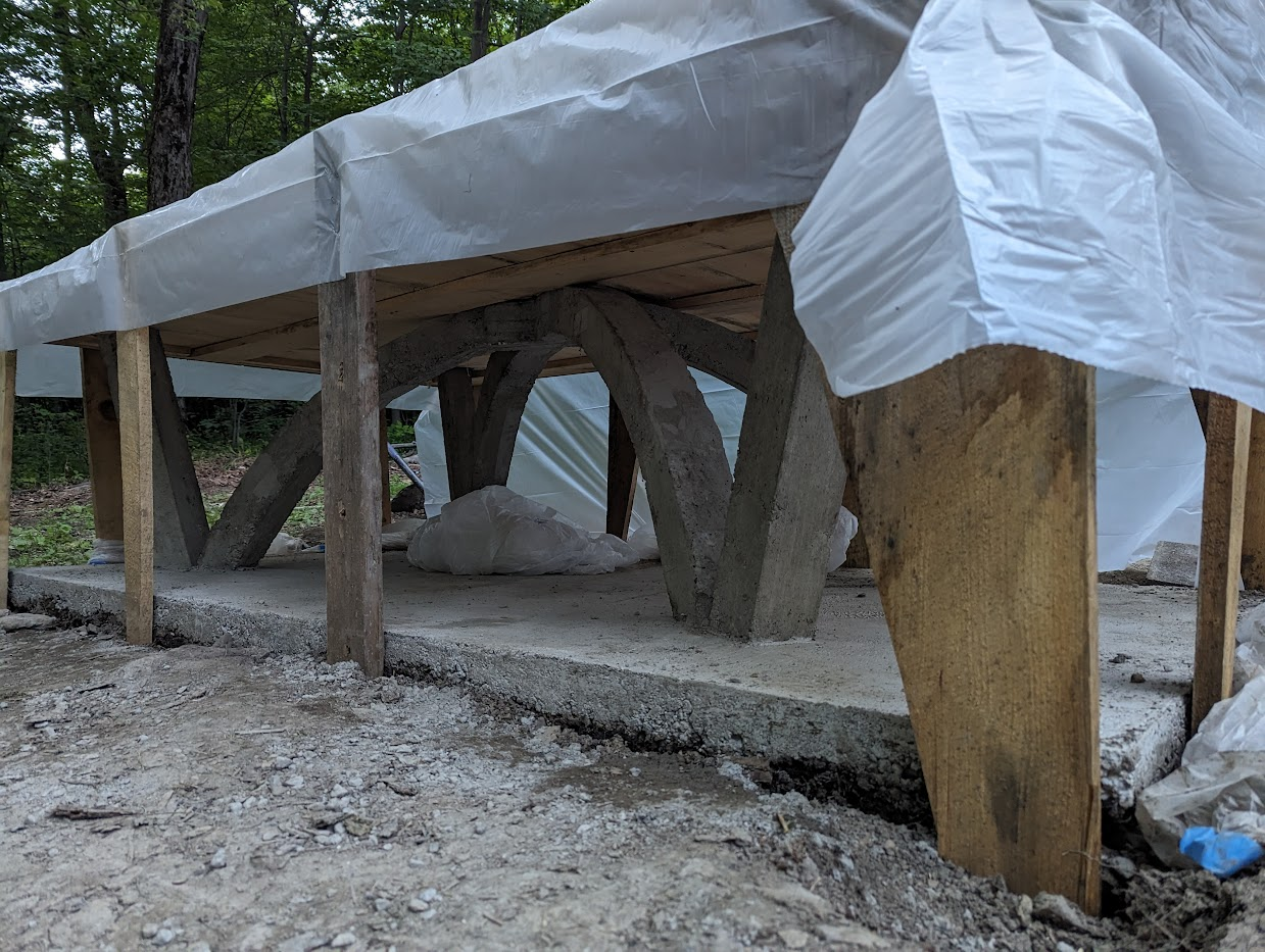
Next, we set up a form for the base. The same form was used later for the tabletop. We placed #3 FRP rebar inside the form, at 10 inches on-center.  The arch form and leg forms were placed and cast directly in the concrete of the base.


After the base cured for a few days, we set up the mold for the tabletop. The mold was filled with basaltic FRP mesh reinforcement and also #3 FRP rebar, for tensile reinforcement.  The rebar was located so that it aligned with the legs underneath, for strength. The entire mold was greased with Crisco, used as a mold release agent. A sheet of plastic was placed on top of the wooden form, to help the concrete release from the mold.


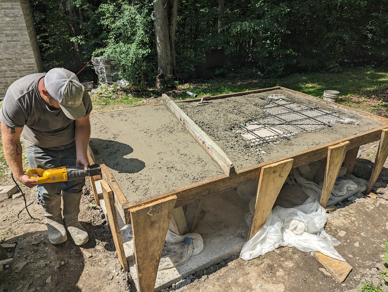
The mold was then filled with concrete, with particular attention to place some concrete under the rebar, to help provide proper cover.  The concrete was then screeded (spread evenly with a straight piece of wood, moved back & forth as it is drawn across the form).  This surface was then floated, or smoothed out by hand.  The edges of the form were all vibrated. In this case, we did not have a proper concrete vibrator, so we used a "sawzall" reciprocating saw, which worked pretty well.


Properly floating the surface is important to get a nice, smooth, flat finish.  It is worth spending some time and doing this properly.


The form was then covered and allowed to cure for a full week. It helps to cover the concrete with plastic, so that water remains in the curing concrete to form hydration products.


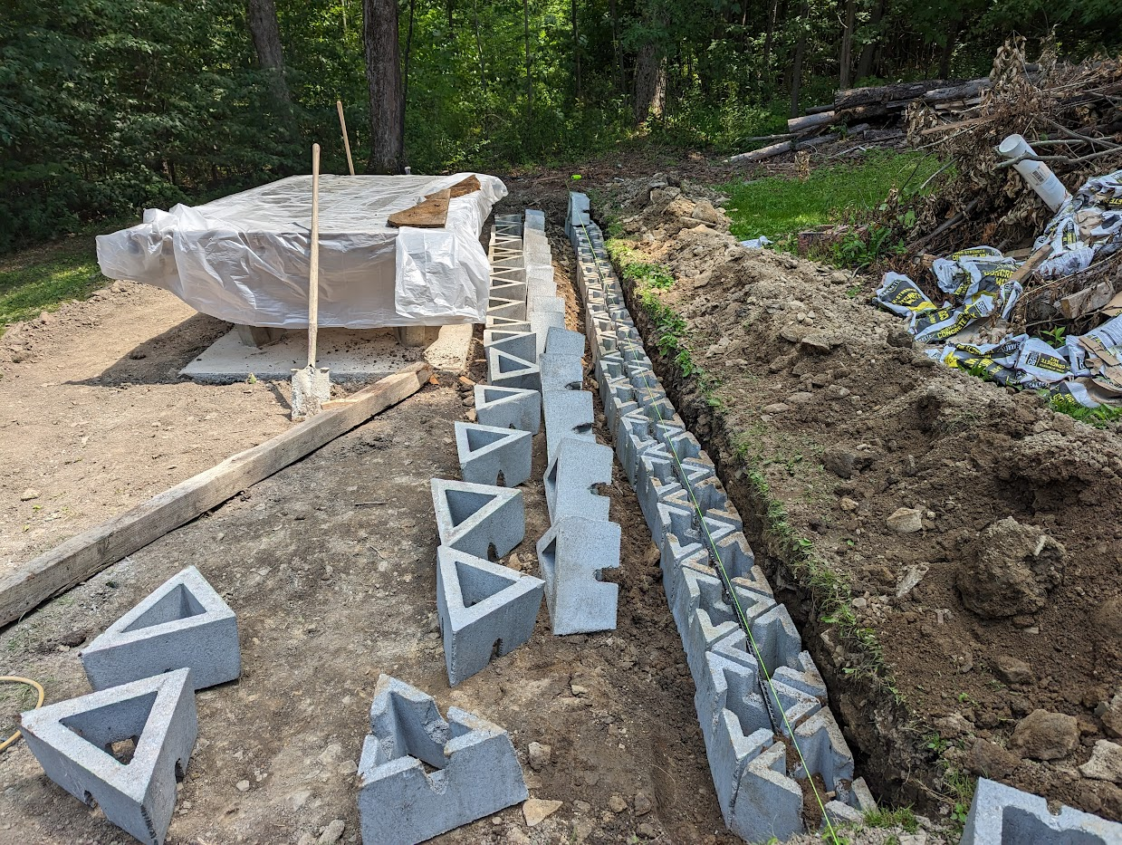
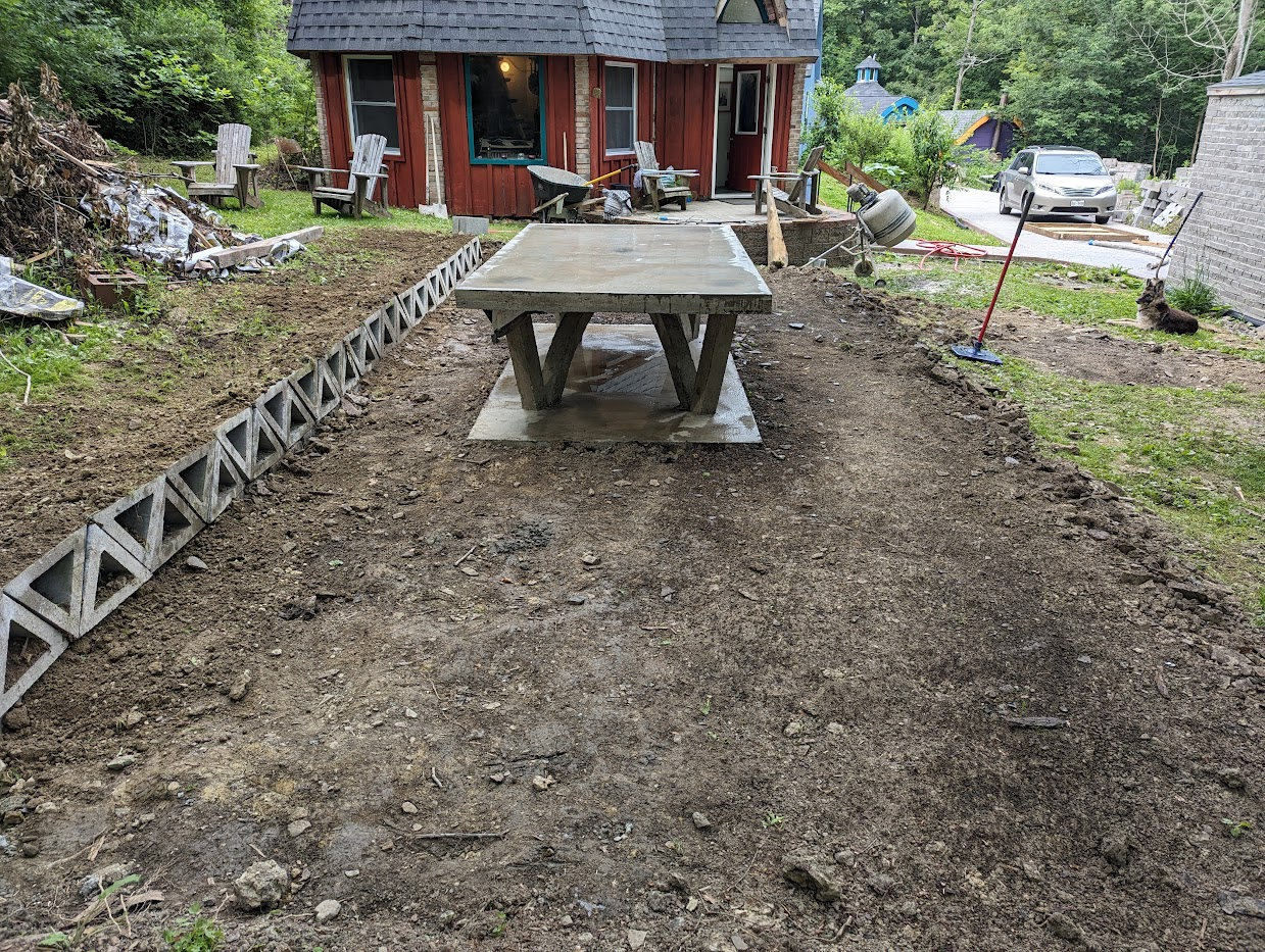
After one full week, the wooden forms were removed. We also did some landscaping, to create a level playing surface on the ground around the table; this involved a retaining wall being placed also.  This work was simply done with a pick, shovel and rake. It took an afternoon. 


Now, it just needs a net! I will also use a sealant to help protect the concrete from the weather, something like Thompson's Water Seal.  This will also make a great picnic table. I expect it should last a long time. We will also plant some grass on the fresh dirt.

This basic concept could be made much larger, to provide an elevated platform to build homes on. We could use my company's masonry arch system to accomplish this, easily and quite affordably.  This would be appropriate for coastal areas which are prone to storm surges and flooding from hurricanes and severe weather. It is stronger than the wooden posts currently used to elevate homes above a storm-surge plain, and will not rust or rot, like wood. It is also more elegant and looks much better than those wooden posts.

This table cost about $150 in concrete.  The rebar is also inexpensive. If anyone wants a concrete ping pong table and would like to borrow my molds, you are welcome to.  Just let me know.

This thing should be fun, I look forward to using it!


Tuesday, November 15, 2022

A recent video

Recently some dear friends of mine completed a lovely video they made about me, my work and my company.  This work was done by Burton Stein, his daughter Autumn Layne Stein, and Autumn's fiance, Matt Goodwin.  I am very grateful to them for this work. 

Here it is!  


Monday, January 17, 2022

Snow covered masonry buildings

 I awoke to a beautiful 15 inches of fresh powder.  I took a few pictures of these masonry buildings covered in snow.  The domes, arches, catenary forms: all seem to create interesting topological snow surfaces.   

Sometimes people will ask about how appropriate a masonry roof is for big snow loads?  They only get stronger with more weight, and the snow also helps insulate even more.  These buildings can handle extreme snow loads.

View out my bedroom window.


Friday, September 3, 2021

Floor, walls and bond beam

 This material is based upon work supported by the National Science Foundation under Grant No. 1660075 ("Topological interlocking manufactured concrete block").  Any opinions, findings, and conclusions or recommendations expressed in this material are those of the author, and do not necessarily reflect the views of the National Science Foundation.

The previous post showed how we excavated, poured the footer and built the stem wall.  Following this, the vertical walls were assembled and the floor was installed. The floors are made to accommodate a radiant heating system. First a rigid foam is laid down, on the level compacted ground floor; then "Pex" TM pipe was installed.  


Concrete was then poured on top of the foam and pex, and screeded level, then the floor surface was floated. 


The walls were built up to header height, then a temporary scaffolding was built for roof assembly.  All exterior doorways had a masonry arch built over them, using wooden forms. The arches are fast and easy to assemble, they are also inexpensive.


After all the vertical walls were assembled, forms were built at the top of these walls; rebar was placed in this cavity as per the PE specification, and the form was poured with concrete to create a reinforced bond beam. 


With the bond beam made, roof construction was about to begin.  That's what I'll describe and show next..