Showing posts with label interlocking. Show all posts

Friday, August 18, 2017

Building Another Masonry Prototype

This material is based upon work supported by the National Science Foundation under Grant No. 1547958.  Any opinions, findings, and conclusions or recommendations expressed in this material are those of the author, and do not necessarily reflect the views of the National Science Foundation.

One year ago (late summer, 2016) I began working on a masonry prototype which would use the novel topological interlocking manufactured concrete arch block, described and discussed here.

I had been teaching a Senior Project engineering class at Alfred University's Inamori School of Engineering, and asked my students to help design this structure.  The students I had the pleasure of teaching include undergraduate students Pavel Boyuk, Patrick Byrne, Wanrui He, Nolan Jessop, Sanket Patel, Nick Roberts and Alex Wessner; under their professor Dr. Ehsan Ghotbi, and also graduate student Martin Monk under his professor Dr. William Carty.

Here are some of the drawings these students did for this structure.  The actual design was changed somewhat from these drawings to what was actually built. These changes include switching from a round profile to a catenary profile on both the main arch for the roof, and also on the flying buttresses which are located on either side of the building.  I also went from seven buttresses per side (as per the students' drawings) to six buttresses.  Finally, I also included two Gothic windows on one side of the main arch.


This building was erected on my own personal property in Alfred, New York. Site preparation began with felling several trees and clearing the logs from the site.  I'll just let the pictures tell the rest of the story, beginning with the building site as it was.


This is the retaining wall, built around the site.


Retaining wall behind, foundation (footer) in the front.


Lots of gravel for proper drainage, very important.


Vertical walls erected.


Those are the flying buttress foundations, on the left.


The slack chain hung in the picture below was used to create the catenary form for the flying buttress.  This is much stronger than a simple, round form.  This shape was traced onto a piece of plywood, the plywood was cut, flipped upside-down, and used as a guide form.


This shows my method for assembling the flying buttresses.  These went up quickly, each flying buttress took around one hour for me to assemble.


This shows the scaffolding, made from the trees which I cut down from this same site.


Here is a concrete block delivery truck, placing block on the scaffolding.  The scaffolding held around 50 tons!


Here is how I made the catenary form for the roof.  I traced the curve made from the slack hanging rope onto wood, and cut out that shape.  I then flipped this shape upside down, and used it as a guide to assemble the roof.


Gothic windows on the side of the structure.


I covered the arch in wood, so that I could apply conventional tarpaper and shingles.


Here is the inside of the structure.  It's an interesting space inside, very roomy.
Here is a concrete 'apron' for the beginning of the driveway.  This will have a pattern stamped concrete driveway, which is about to be made.
These trenches for drainage are 4 feet deep, and hook up to a large drainage pipe.


Here I am beginning to apply architectural shingles.  This building is almost complete.


This was an exciting and fun project.  Much was learned, this first prototype is somewhat crude, since it was a first attempt.  The arch span is over 25 feet, and the depth of the arch is over 30 feet.  The reader should also note that while I was building this, I simultaneously wrote and filed a patent, wrote a Phase II Proposal for the National Science Foundation (successfully, it was funded) and several other large tasks at the same time.  This building actually went up very quickly.  They will only get better!


Wednesday, January 21, 2015

R&D in Concrete Block Masonry

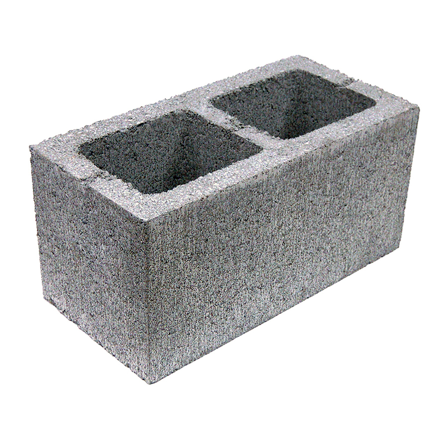
Manufactured concrete block represents a great success story of the 20th century.  An entire global industry has developed and evolved into a high state of efficiency and economy, all based on manufactured concrete block.  This technology thrives in virtually every country on earth: the traditional, rectangular concrete masonry unit (CMU) is produced inexpensively and with an engineering knowledge which is well understood and successfully put into practice by block producers globally.  The result is something we all tend to take for granted: high-strength, consistently dimensioned, inexpensive, rapidly produced CMU’s which are suitable for vertical walls in virtually any type of building, including residential, commercial, public buildings and infrastructure.  With such a successful model of production, distribution, assembly and availability already well established and in place, what –if any- new developments can research and development (R&D) add to this existing industry and practice?
My own work as a masonry designer has addressed this question for 25 years now.  I will attempt to summarize the areas of potential future growth, development and design which this robust industry has left essentially unfulfilled.  A look at current areas of research conducted by various segments of the scientific and engineering world indicate areas which stand to benefit and develop rapidly from the existing engineering practices of the concrete block industry.  The research and development proposed here hold the potential to transform the concrete block industry’s offerings into an entirely new realm of products which will provide better building systems at a lower cost on a global basis.  A modest effort in research and development will reap huge benefits for humanity; it will grow the concrete block industry and make superior, affordable, beautiful and holistic construction available for all.

One specific area of current research which has garnered significant attention from scientists, engineers, designers and practitioners is the idea of topological interlocking structures.  “Topological” refers to “Topology (from the Greek τόπος, "place", and λόγος, "study") [which] is the mathematical study of shapes and topological spaces. It is an area of mathematics concerned with the properties of space that are preserved under continuous deformations including stretching and bending, but not tearing or gluing. This includes such properties as connectedness continuity and boundary.  Topology developed as a field of study out of geometry and set theory, through analysis of such concepts as space, dimension, and transformation. Such ideas go back to Leibniz, who in the 17th century envisioned the geometria situs (Greek-Latin for "geometry of place") and analysis situs (Greek-Latin for "picking apart of place"). The term topology was introduced by Johann Benedict Listing in the 19th century, although it was not until the first decades of the 20th century that the idea of a topological Space was developed. By the middle of the 20th century, topology had become a major branch of mathematics” (taken from Wikipedia).
Currently, concrete block design and practice do not provide for topological construction.  The standard rectangular concrete block designs (with which we are so familiar) can only be used to create straight vertical walls and square corners.  A few designs allow for a slightly curving wall, which have found use mainly in retaining walls and landscaping applications.  Other novel designs allow for slight variations to the basic idea of a vertical wall, including corners which occur at 45 degrees and so on.  Current concrete block designs are far from providing a full expression of topology.  Curving walls –such as those provided by landscaping applications- only curve in one dimension, like a cylindrical surface, and do not allow curvature in two dimensions, like a spherical surface.  A form of concrete block known as “articulated block” (shown above and below) does some interesting work as an erosion-arresting embankment material.  Articulated block do not interlock in the plane being assembled; blocks can slide in and out of the assembly.   There are some great articulated block designs being developed though.

The design of CMU’s which allow for full topological expression provides the ability to use block to make roofs and complete curved structures (e.g. complete spheres, ovals, elliptical, catenary and other designs).  The design ability which can create a full expression of topology allows the use of high strength, affordable, rapidly produced building components which provide all the benefits of concrete block, including: fire resistance, termite resistance, rot resistance, building longevity, resale value, solidity, appearance, and the ability to withstand extreme weather events (hurricanes, tornadoes, typhoons, storm surges, tsunamis, etc.).    The creation of CMU designs which allow for full topological expression will create an entirely new architectural vocabulary for building with concrete block, and will create entirely new markets for concrete block.
If an interlocking aspect is included in the masonry unit then the topology in masonry is made particularly more effective.  One striking example (which has fueled much of the current research) is the failure of thermal tiles on the space shuttle Columbia.  Because they did not interlock, these topological tiles (designed to wrap around the shuttle: topologically) were free to move and dislodge themselves from their protective positions since they were held in place only by adhesive, leaving the shuttle vulnerable to catastrophic reentry into the earth’s atmosphere.  Researchers were quick to realize that if an interlocking aspect of each masonry unit (or tile) were incorporated, then the geometry of the individual masonry units would have helped keep them in their proper location (anchored by adjacent masonry units) and prevented them from being removed.  Furthermore, researchers have realized that topological interlocking masonry units (or tiles) would not suffer complete, systemic failure if one of these masonry units were damaged: the other adjacent and surrounding tiles would stay in place, even if one tile broke or was removed.  By including the interlocking feature into the masonry unit itself, a separate independent connector is not required.


While this idea of the beneficial nature of interlocking masonry units is illustrated by the Columbia tragedy, it holds great significance for the less exotic application of buildings here on terra firma.  To fully understand this, we will look at the current state-of-the-art for masonry engineering analysis.  Examining a masonry arch, the current engineering model makes 3 assumptions: 1. Masonry units have infinite compressive strength; 2. Masonry units have no tensile strength; 3. Masonry units never slide against each other (they remain in their fixed position).  We will concern ourselves here with the third assumption, the idea that masonry units in an arch (known as voussoirs) never move relative to one another.


In reality and in practice, voussoirs are known to move against each other in a masonry arch.  When this occurs, the arch can be significantly weakened and this movement of voussoirs can result in failure and collapse of the arch.  A catenary thrust line is an imaginary line of force which exists in the wall thickness of the arch.  Catenary (from Latin “catena” or chain) is the shape of a hanging chain or cable under gravity; if this shape of a hanging chain is inverted, then a catenary thrust line is generated.  As long as this imaginary thrust line does not touch or exit the arch wall thickness, the arch will remain standing and stable.  If the imaginary catenary thrust line touches or exits either the inner surface (intrados) or the outer surface (extrados) of the arch, then a hinge will form at that location.  Several hinges allow a mechanism for movement of the arch, resulting in a buckling or folding of the arch about these hinge locations, leading to failure and collapse of the arch.  However, if voussoirs possess an interlocking feature such that they are not free to move relative to any adjacent (interconnected) voussoirs, then the catenary thrust line will not touch or exit either the intrados or extrados of the arch due to movement.  Thus interlocking masonry units in an arch are fundamentally much stronger, more robust and more stable than masonry units which do not interlock.
The creation of an effective interlocking feature on a topological masonry unit produced on a standard conventional block machine is a very real challenge for the masonry designer.  Interlocking features are actually commonplace in standard (non-topological) blocks: the ‘top’ and ‘bottom’ of the concrete masonry unit can readily incorporate interlocking features.  A wide variety of designs is possible if the interlocking feature does not include topological arrangements, but the designer is still limited to building straight vertical walls.  In order to provide an interlocking feature for a topological masonry unit, the sides of the block must be used (not just the ‘top’ and ‘bottom’ of the block) as sites of interlock.  The difficulty here is that a block mold must be readily stripped from the block without any undercut, or draft, or negative angle.  In other words, an interlocking feature on a topological block will create undercuts: an interlocking topological block simply will not release from a mold.  This contradiction can be overcome by symmetry and design.

Another difficulty in creating an interlocking topological block on a block machine is the ability of the mold cavity to be filled completely, evenly and homogeneously.  If a section of the mold near the ‘bottom’ of the block has an overhanging feature (steel mold above it) then it will not fill as readily as an open cavity which allows the concrete mix to flow into it, unimpeded.  A section of mold cavity which has an overhanging feature will impede the flow of concrete into the cavity, resulting in segregation of aggregate.  This segregation of aggregate will typically result in a weakened section of the block where larger aggregate is prevented from filling as easily as in an open mold cavity.  Lack of larger aggregate in a filled mold section creates a weaker section of concrete as a result.

In addition to sections of mold being less than ideally filled due to overhanging mold parts, there is another problem where a section of mold cavity at the ‘top’ of the mold has an open space below it (at the ‘bottom’).  This will create an overhanging projection of block, which is unsupported from underneath (at the ‘bottom’).  These cantilevered features of block are prone to cracking and breaking, especially upon handling as the un-cured block leaves the block-making machine. 
How can a topological interlocking masonry unit be created in a manner that provides adequately filled mold cavities at the ‘bottom’ of the mold, while also not creating weak cantilevered sections at the ‘top’ of the mold?  This is a very interesting design challenge; one which I hope will attract the efforts and solutions of other designers.


Catenary thrust line analysis of masonry domes is another area of current research.  Computer models which digitally process the applied stress and the resulting strain as hinge mechanisms are used to develop visual models.  Catenary thrust line analysis is also used to digitally analyze a computer 3D model as a tool for designing buildings.
Biomimicry/Biological Design as a source of masonry design is ripe with potential.  “Nature’s masons” include single-celled radiolarian and foraminifera, coral, sea anemones, sea horses, turtles and tortoises, Thor’shero shrew, and an endless array of life’s other innovative design solutions.
Anisotropy in manufactured concrete block has not been fully utilized with current block designs.  Vertical block walls are made with the weaker axis of the block facing horizontally, to the outside.  It is possible to orient the block so that the high strength axis faces outside, resulting in a significantly stronger building.
Robotic assembly is still in its early stages regarding masonry, but real progress continues in this field.  Robots may play an important role in the future of masonry.  Robotic assembly may have an early adaptation for situations that might endanger a human mason, such as radiation or other hazardous materials.  Construction Robotics is one company that is currently successfully developing robotic masonry.


3D Printing is also in its early stages, but is expected to develop with time.  3D printing should find early use in masonry applications which require a unique masonry piece, such as at the intersection of two arches, or to allow conduit or openings, etc.   In this role it will be cost effective fairly soon.

Saturday, January 19, 2013

Topological interlocking structures

I recently came across an interesting paper done by a team of physicists and mathematicians titled The Concept of Topological Interlocking in Engineering  by AV Dyskin, Y Estrin, E. Pasternak, HC Khor andAJ Kanel-Belov of the Department of Civil Resource Engineering, the University of Western Australia, Australia; Institut fur Werkstoffkunde und Werkstofftechnik, Technische UniversitatClausthatl, Germany; and Unversity of Bremen, Germany (Materials Science and Engineering, Volume 31, Issue 6,August 12, 2011, pp.1189-1194).

The work described in this paper by this team is very similar to some of the work I have been conducting over the past 20 years or so.  First, they identify their inspiration as occurring in the biology of nature, as I have also done (see “Nature’s Masons” on this blog). 

Secondly, they describe how a structure assembled from their interlocking units is toughened, as it is resistant to crack propagation between adjacent interlocking units (as I have also described several times on this blog, e.g. “Harder, stronger, stiffer, tougher”). 

Third, they provide a rounded edge to their interlocking shapes, so as not to focus stress, as I have also described on this blog (see “The art of limits (and the limits of art”).
 

The authors point to the failure of thermal tiles on thespace shuttle Columbia as one example of how their concept of “topological interlocking” can be advantageous by providing a toughened structure held together by geometry alone; which is at the very heart of my own work.  The authors' system is comprised of parts interlocked with the concave features of one block interlocking with convex parts of another block, and vice-versa.  This is precisely how my dual-inverse mirror plane (dimp) arrangement works also. 

They assembled flat (planar) sections of structure using various polyhedral arrangements and tested these for strength.  They found that the resulting planar configurations could withstand significant stress tests, and furthermore that loss of one or more interlocking block did not necessarily result in failure of the structure.  Again, this is what I have been saying about my own system for years.

The work of this team is very interesting, and validates and substantiates much of what I have been saying for years.  Their system does lack a few of the advantages to be found in the designs I have developed.  First, their topological interlocking units create an undercut, or draft, or negative angle which cannot be readily released from a simple two-piece mold (unlike my system).  Secondly, their system is not capable of conjugate shearing in the same ease of manner which triangular shapes inherently allow.  Third, they build flat planar structures, and their system does not allow for a radial (spherical and cylindrical) structure as readily, as easily and as strongly as my system does (my system can also do flat planar structures).
 

I was delighted to see this work and realize that other teams of engineers share the same insight into the advantages inherent in a system comprised of interlocking unit shapes.

Tuesday, September 27, 2011

Ceramic Spheres: a Work in Progress


I am currently preparing to make a series of fired ceramic masonry spheres, around 3 feet in diameter.   These spheres will utilize the interlocking triangular design which I’ve developed over the years.  The image below is from an electronic file created by my business partner, Mike Wong.  This same file will be used to produce the master shape from which molds are made.

I plan to produce the ceramic shapes from plaster molds.  These molds will be made from a CNC (computer numerically controlled) machined master shape.  I expect the master shape to be made from wood.  The key to doing this efficiently is to cast the ceramic parts from a simple two-piece plaster mold.  More than two parts for a mold makes production difficult, time consuming and expensive.  Below are images of blocks made from a two-piece mold for a kiln I made, as discussed here.


The geometry I’ll be using for this sphere is that of an icosahedron.  There are twenty pieces in an icosahedron, each is an equilateral triangle.  The shapes will be curved, like those on the right, below:

I’ll probably use a series of thin metal bands on the outside of the sphere to help hold the sphere together and make them easy to transport.  I expect these to look pretty cool, like a modular spherical UFO of a barbeque!

These complete spheres will have a rectangular door on the side.  I plan for this door to be a simple hinged arrangement, with a hinge at the bottom. 

These spheres can be used for pizza ovens, barbeques, smokers, or simply as ovens.  I’m curious if anyone reading this can think of another use for this sized sphere?

I plan to configure these so that they can run on propane, natural gas, wood or charcoal.  I plan to have the burner port on the bottom and the vent/chimney on the top.  I also plan for the flame to be slightly tangential (offset from center) so that a swirling vortex is developed within the firing space.  This extends the flame path, creates more even temperatures, and increases efficiency.

The thermal mass effect of the ceramics will help provide radiant heat and even temperatures throughout the firing space.

I will post additional entries on this forum as the project moves along.  Right now I have around 25 tons of clay sitting in my driveway, which I’ll be using to make these spheres (right now I'm racing against winter!).  If all goes well, I should be able to make between 500-1,000 of these spheres.  This should be fun!

[Here is an update on this project]