Showing posts with label catenary. Show all posts

Sunday, February 26, 2012

Catenary reconsidered


Application of catenary structures must be carefully considered for use in different environments.  A few examples worth looking at include:

·        An environment without gravity.  If a structure is built in space, or acts as a satellite, or is built in conditions of very low gravity (like on an asteroid, or the moon, or even a buoyant ball) then the reasons for a catenary structure practically disappear.  Under these conditions a sphere or spherical dome is the optimal structure.


·         Very high external pressure.  If a structure is submerged to any depth, then an outside compressive force acts on the entire structure.  Under these conditions, again we find that a sphere is the strongest and most stable structure.  A catenary structure under great external pressure is weaker than a spherical structure.  (Do you ever crack an egg at the tip? No, you crack it on the weak side.)

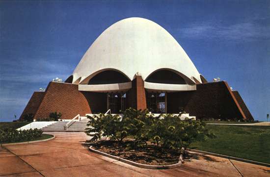
·         Extreme loading from high velocity winds.  Such conditions are found in extreme storms, including hurricanes, typhoons, and tornadoes.  Under these conditions, the exposed surface area per unit volume is minimized by using a spherical form.  The profile is further minimized by using only a smaller segmental section of the spherical form, further reducing the profile of the structure.  A woven tensile geodesic web will help blocks resist suction forces in very high winds.

·         Earthquakes.  A catenary arch results from acceleration due to gravity.  In an earthquake, the ground can move in a sudden sideways fashion.  This results in acceleration in a sideways or lateral sense.   If a chain hangs from a rod, and the rod is tipped or inclined away from horizontal, then the catenary changes relative to the rod: the same way thrust force lines in a dome change relative to the horizontal ground movement during an earthquake. 

This situation is as if the arch was built on an inclined surface; the catenary still exists, but it is like a catenary on an inclined surface.  The direction of the inclined surface is relative to the motion of the ground.  The result of this sideways acceleration is that the catenary arch may eventually touch or exit the wall thickness; a hinge is created and the structure will buckle and collapse. 

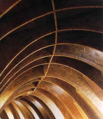
Catastrophic failure of masonry arches during earthquakes can be prevented by using tensile elements woven into the arches as great circle arcs.  This geodesic tensile web will prevent the creation of hinges, catenary thrust force lines will not exit the wall thickness due to lateral acceleration.   Structural integrity is maintained if the hinges cannot open.   Tension is provided.

Tensile elements woven into a dome will help hold it together during an earthquake.

Tuesday, February 21, 2012

Catenary domes

The catenary form is key to understanding the design of masonry arches.  As discussed here, here, and here, “catena” is Latin for “chain.”  This word origin serves as a useful tool in analyzing the catenary arch.  This is because a chain hung slack is an exact analogy for a masonry catenary sprung arch, only it’s the opposite.  “Up” in a slack chain segment is “down” in sprung masonry arch; “tension” in a slack chain segment is “compression” in a sprung arch segment.  This fact provides insight by simply hanging a chain (or chains) and observing.


Some architects and designers use the term “funicular” when describing catenary arches.  Funicular comes from the Latin “funis” meaning rope or cable.  In terms of masonry, catenary is more accurate than funicular because the individual links of a chain are analogous to the individual blocks (voussoirs) of an arch; rather than the smooth continuity of a rope or cable.


A small chain will behave exactly as a large chain, in a proportional sense.  This reflects the scaleability of masonry arches, as discussed in earlier entries on Galileo’s wrong application of his Square Cube Law to masonry arches.  This means that application of Galileo’s Square Cube Law to chains is also wrong.  Chains are scaleable and do not need to be redesigned to be made larger.  Small models using small chains have direct application for larger models using larger chains.  Since the chain is a direct representation of the catenary arch, large masonry arch structures can be represented by small chain models.  Antoni Gaudi used this method to model the Sagrada Familia, as shown below.


Thrust force lines are the imaginary lines that indicate where the compressive force in a voussoir or block is located in the thickness of the arch.  In an arch, the thrust lines always describe a catenary curve.  If the thrust lines touch the inside (intrados) of the arch or leave the wall thickness, then a hinge is created and the arch or dome will buckle out and collapse.  If the thrust lines touch the outside (extrados) of the arch or exit the wall thickness, then a hinge is created and the arch or dome will buckle in and collapse.   In any masonry arch that stands, the catenary thrust lines are kept within the wall thickness; if thrust lines touch or leave the wall thickness then the arch collapses.


If thrust lines can be kept within thin walls, then wall thickness can be reduced.  There are different ways to keep the thrust lines within a thin masonry shell:

·         A smaller section of a dome can be used.  This smaller dome section creates an outward thrust or splay which must be contained by either buttressing the outside of the arch, or by having a tensile element inside the arch.  


·         If a half round arch is used, the thrust lines will be either close to, or touching, (or beyond) the intrados at a location in the arch known as the haunch.  By applying an external load to the extrados (outside) of the arch at the haunch, the thrust line is brought back toward the middle of the wall thickness.  By applying an external load (e.g., fill, rubble, etc.) to the outside of the haunch in a round arch, the arch can be kept relatively thin (this is somewhat counter-intuitive: that adding weight makes it stronger).   


·         Wall thickness can be reduced dramatically by simply making the dome as a catenary shell.  That is, instead of building spherical domes, they are made more “pointy” like the small end of an eggshell.  By making a catenary arch, the catenary thrust lines are kept within a very thin wall.


From a masonry perspective, the difficulty in assembling a catenary dome lies in the large number of different unit shapes required to make it.  The advantage of a spherical masonry system lies in the small number of triangular unit shapes needed to build a dome; they are all interchangeable (unlike a catenary dome).  Catenary arches can be made with different profiles, depending on how much slack the chain has.  Selection of the catenary arch which comes closest to a circular arch is advantageous.  By accounting for the slight differences in a true spherical dome and a catenary dome, assembly of a structure which comes very close to a true catenary can be achieved from triangular masonry units.  This is done by varying the thickness of mortar (or gasket material, as described here) and dihedral angles between voussoirs slightly as they are assembled.  This is most easily achieved by using a catenary-shaped form or support or bracing for the voussoirs to be assembled against.

In earlier entries (here and here) I discussed using an inflatable bladder as a form to support masonry units as they are assembled into a dome.  It is a simple modification to change a hemispherical bladder into a catenary-shaped bladder which can be used to support block as they are assembled into a catenary dome.  A dome with the thinnest walls, using the fewest number of unit shapes, in the strongest possible configuration is provided by using this method.

Wednesday, July 21, 2010

Lessons learned from Galileo's mistake

For the past two entries on this blog, I looked at Galileo’s valuable insight known to us today as the Square Cube Law. Galileo made the mistake of applying the Square Cube Law to masonry arches. He said (p.33) “The great Master Builders of the past used proportional design rules, which are essentially incorrect. Using these rules they built masterpieces of architecture and engineering of the past.” But it was Galileo who was essentially incorrect.


As we wrap up our discussion of Galileo’s incorrect application of the Square Cube Law, a few things stand out from the insight gained by a correct analysis of arches, stresses, and load-bearing ability.

First, the important concept of a catenary is made even more emphatic, and trumps the role of the Square Cube Law. As discussed earlier, a catenary comes from the Latin word “catena” which means chain. Architects also use the term “funicular” to describe the catenary curve; from the Latin “funis” meaning rope or cable. When speaking of masonry, “catenary” is actually a more accurate term, because a masonry arch is comprised of voussoirs, or individual masonry blocks, which are analogous to the individual links of a chain; not the smooth continuity of a rope or cable.

In every arch which is built and stays standing, there can be traced a catenary curve within the wall thickness, described by the thrust force lines which represent the force of gravity acting on the voussoirs. If this catenary curve goes outside of the wall thickness, then a hinge is created, the arch will buckle at this hinge, and it will collapse.

As long as the catenary curve fits within the wall thickness, walls can be made thinner and thinner. Furthermore, the addition of loads onto a masonry arch tends to keep the thrust force lines within the wall thickness: so that adding weight can actually strengthen a masonry arch or dome.

This is the essential design analysis for masonry arches and domes. It really has nothing to do with Galileo’s Square Cube Law. Whether by conscious design and intuitive insight, or merely by trial and error, the master masons of antiquity always fit the catenary curve within their wall thickness by using their simple rules of geometric proportion; this is why their structures could be made small or large, and this is why their incredible feats of engineering and art still stand today to inspire us and enrich us.

Tuesday, July 20, 2010

More on Galileo and Master Masons

In my last blog entry, I began a discussion of an article by Santiago Huerta, Galileo was Wrong! the Geometrical Design of Masonry Arches, Nexus Network Journal, Volume 8, No. 2, 2006.  The link to this article is worth taking a look at; Dr. Huerta uses many excellent illustrations to demonstrate his salient points.


Dr. Huerta provides some valuable insight into the engineering analysis of masonry domes and arches. He argues that the proportional design of arches, as used by master masons of antiquity, has provided a tool for arch construction which has proven successful and is more accurate than the approach first described by Galileo in his famous paper “Dialogues Concerning Two New Sciences” of 1638.

If we look at the components that comprise a masonry arch, known as voussoirs, and perform an analysis of their thrusting forces under gravity, the resulting thrust line analysis provides critical insight into the strength of masonry arches. I briefly referred to this method of analysis in an earlier blog entry while discussing Gothic arches, using the illustration below.

The thrust lines may be drawn to represent the gravitational forces acting on the individual voussoirs within the arch. As long as these thrust lines are within the wall thickness of the arch, the structure is stable, and will remain in a static state of equilibrium.

Master masons of antiquity, in using their geometrical approach (as discussed in my last entry) consistently provide a structure wherein the thrust line analysis yields a stable structure in equilibrium. This analysis remains consistent even when the structure is scaled up, or made much larger. This scale ability is in direct contradiction to Galileo’s “Square Cube Law” which states that as scale increases, the design must account for the fact that while cross sectional area of material increases as a squared function, the volume (and hence mass) increases as a cubed function.  This relates directly to the concept of Allometry, or the relationship between size and shape.

This insight –and refutation of Galileo- has some profound implications for analysis and design of masonry arches. Thrust line analysis is different than other methods of stress analysis within a structure. One common method of stress analysis today is Finite Element Analysis, as performed by students who did work on my masonry system and provided their own Finite Element Analysis, as shown here several entries ago. A thrust line analysis is superior to Finite Element Analysis in providing specific tools and insight into masonry arch construction.

In performing a thrust line analysis on a masonry arch, it becomes obvious that if a circular arch (or barrel vault) or hemisphere (or dome) is built, the thrusting forces (pushing out) are greatest toward the bottom of the vault, or dome, or hemisphere. This is accommodated by simply making the wall thicker, so as to keep the thrust lines within the (thicker) wall. Taking this approach a step further, if the arch, or dome, or hemisphere is truncated at the base, or taken as a smaller section which is less than a full hemisphere, then the entire arch wall may be made substantially thinner: because the thrust lines no longer go to the bottom of a full semi-circle (where they splay out) and can be kept within the wall thickness of a thinner wall. The key to performing this arch truncation in a structurally sound manner is to provide a thick abutment at the base of the dome section, so that thrusting forces are resolved here. This insight allows for arches and domes to be made substantially thinner.

The insight of thrust line analysis is ultimately a succinct and quantified summary of the reasons for building arches as catenary arches, as discussed earlier in this blog.


Saturday, July 10, 2010

Antoni Gaudi

“Antoni Plàcid Guillem Gaudí i Cornet” is the Catalan pronunciation of the full name of the artist and architect known to us as Antoni Gaudi (1852-1926). Gaudi is a noteworthy modernist and unique visionary who worked largely on designs gleaned from observation of nature.


His work often used parabolic, hyperbolic and catenary arches; using steel reinforced concrete.

Gaudi used masonry and tile work with an incredible facility of complexity which produced effects almost hallucinatory. He brought life to masonry.

Gaudi was deeply religious; his great unfinished work is the “Sagrada Familia” which is scheduled to open in 2026, the 100th anniversary of his death. The church is to be consecrated by Pope Benedict XVI on November 7, 2010.

Here is Gaudi speaking of Gothic:

"Gothic art is imperfect, it means to solve; it is the style of the compass, the formula of industrial repetition. Its stability is based on the permanent propping of abutments: it is a defective body that holds with support... gothic works produce maximum emotion when they are mutilated, covered with ivy and illuminated by the moon."


An interesting footnote: during the Spanish Civil War, many luminaries of the 1930’s became aware of Gaudi's work; including George Orwell. Gaudi and Orwell are two heroes of mine (one usually wants their friends to get along) but Orwell hated Gaudi’s work. C’mon George, lighten up.

Tuesday, May 11, 2010

Arch designs: Corbels and Catenaries

We’re taking another small detour from description of applications for the masonry system I’ve developed to talk about some fundamental aspects of masonry. Yesterday we looked at thermal mass, today we’ll take a look at types of arches; another important aspect to this masonry system.


Very early in the development of masonry in the ancient world, masons developed what is known as a corbel arch. A corbel arch is not a “true” arch because it uses blocks that are cantilevered, and do not transfer the load directly down the arch. Corbelled arches are found in ancient Irish, India, Mayan, Greek, and Cambodian architecture.

Here’s a good description of corbelled arches from Wikipedia:
“A corbel arch (or corbeled / corbelled arch) is an arch-like construction method which uses the architectural technique of corbeling to span a space or void in a structure, such as an entranceway in a wall or as the span of a bridge. A corbel vault uses this technique to support the superstructure of a building's roof.


A corbel arch is constructed by offsetting successive courses of stone at the springline of the walls so that they project towards the archway's center from each supporting side, until the courses meet at the apex of the archway (often capped with flat stones). For a corbeled vault covering the technique is extended in three dimensions along the lengths of two opposing walls.

Although an improvement in load-bearing efficiency over the post and lintel design, corbeled arches are not entirely self-supporting structures, and it is sometimes termed a "false arch" for this reason. Unlike "true" arches, not all of the structure's tensile stresses caused by the weight of the superstructure are transformed into compressive stresses. Corbel arches and vaults require significantly thickened walls and an abutment of other stone or fill to counteract the effects of gravity, which otherwise would tend to collapse each side of the archway inwards.”

A much better arch design is a catenary arch. “Catena” is Latin for “chain.” If a chain is allowed to hang with some slack, and if the links of the chain are welded together and the chain is flipped upside down, the resulting curve is a catenary curve.
Here’s a good discussion of catenary from Wolfram Mathworld:

“In 1669, Jungius disproved Galileo's claim that the curve of a chain hanging under gravity would be a parabola (MacTutor Archive). The curve is also called the alysoid and chainette. The equation was obtained by Leibniz, Huygens, and Johann Bernoulli in 1691 in response to a challenge by Jakob Bernoulli.

Huygens was the first to use the term catenary in a letter to Leibniz in 1690, and David Gregory wrote a treatise on the catenary in 1690 (MacTutor Archive). If you roll a parabola along a straight line, its focus traces out a catenary. As proved by Euler in 1744, the catenary is also the curve which, when rotated, gives the surface of minimum surface area (the catenoid) for the given bounding circle.”

Catenary arches are the strongest possible arch under gravity. Catenary arches are commonly used in gas-fired kilns. They are found across many cultures and civilizations around the world. An interesting example is Musgum architecture found in Cameroon, Africa. These beautiful structures seem naturally derived, and are a fine example of using this optimal arch design to build houses.

If a slack chain is allowed to settle into a shape approximating a spherical curve, it gets pretty close. Thus a spherical dome is not too far from a catenary arch, and provides some indication that a spherical section is a strong arrangement.

In an environment with little or no gravity, the advantages of a catenary arch disappear, and a spherical structure stands alone as the strongest and best design for a shelled structure.

This opens the door to extraterrestrial applications, which we’ll be looking at tomorrow. Sounds like science fiction, but it’s really not.