Subscribe To


 Posts
All Comments
Posts
All Comments
Showing posts with label dome. Show all posts
Showing posts with label dome. Show all posts
Thursday, September 26, 2019


Sunday, February 26, 2012
Catenary reconsidered
Application of catenary structures must be carefully considered for use in different environments. A few examples worth looking at include:
· An environment without gravity. If a structure is built in space, or acts as a satellite, or is built in conditions of very low gravity (like on an asteroid, or the moon, or even a buoyant ball) then the reasons for a catenary structure practically disappear. Under these conditions a sphere or spherical dome is the optimal structure.

· Very high external pressure. If a structure is submerged to any depth, then an outside compressive force acts on the entire structure. Under these conditions, again we find that a sphere is the strongest and most stable structure. A catenary structure under great external pressure is weaker than a spherical structure. (Do you ever crack an egg at the tip? No, you crack it on the weak side.)

· Extreme loading from high velocity winds. Such conditions are found in extreme storms, including hurricanes, typhoons, and tornadoes. Under these conditions, the exposed surface area per unit volume is minimized by using a spherical form. The profile is further minimized by using only a smaller segmental section of the spherical form, further reducing the profile of the structure. A woven tensile geodesic web will help blocks resist suction forces in very high winds.

· Earthquakes. A catenary arch results from acceleration due to gravity. In an earthquake, the ground can move in a sudden sideways fashion. This results in acceleration in a sideways or lateral sense. If a chain hangs from a rod, and the rod is tipped or inclined away from horizontal, then the catenary changes relative to the rod: the same way thrust force lines in a dome change relative to the horizontal ground movement during an earthquake.

This situation is as if the arch was built on an inclined surface; the catenary still exists, but it is like a catenary on an inclined surface. The direction of the inclined surface is relative to the motion of the ground. The result of this sideways acceleration is that the catenary arch may eventually touch or exit the wall thickness; a hinge is created and the structure will buckle and collapse.

Catastrophic failure of masonry arches during earthquakes can be prevented by using tensile elements woven into the arches as great circle arcs. This geodesic tensile web will prevent the creation of hinges, catenary thrust force lines will not exit the wall thickness due to lateral acceleration. Structural integrity is maintained if the hinges cannot open. Tension is provided.


Tensile elements woven into a dome will help hold it together during an earthquake.
Tuesday, February 21, 2012
Catenary domes
The catenary form is key to understanding the design of masonry arches. As discussed here, here, and here, “catena” is Latin for “chain.” This word origin serves as a useful tool in analyzing the catenary arch. This is because a chain hung slack is an exact analogy for a masonry catenary sprung arch, only it’s the opposite. “Up” in a slack chain segment is “down” in sprung masonry arch; “tension” in a slack chain segment is “compression” in a sprung arch segment. This fact provides insight by simply hanging a chain (or chains) and observing.


Some architects and designers use the term “funicular” when describing catenary arches. Funicular comes from the Latin “funis” meaning rope or cable. In terms of masonry, catenary is more accurate than funicular because the individual links of a chain are analogous to the individual blocks (voussoirs) of an arch; rather than the smooth continuity of a rope or cable.
A small chain will behave exactly as a large chain, in a proportional sense. This reflects the scaleability of masonry arches, as discussed in earlier entries on Galileo’s wrong application of his Square Cube Law to masonry arches. This means that application of Galileo’s Square Cube Law to chains is also wrong. Chains are scaleable and do not need to be redesigned to be made larger. Small models using small chains have direct application for larger models using larger chains. Since the chain is a direct representation of the catenary arch, large masonry arch structures can be represented by small chain models. Antoni Gaudi used this method to model the Sagrada Familia, as shown below.


Thrust force lines are the imaginary lines that indicate where the compressive force in a voussoir or block is located in the thickness of the arch. In an arch, the thrust lines always describe a catenary curve. If the thrust lines touch the inside (intrados) of the arch or leave the wall thickness, then a hinge is created and the arch or dome will buckle out and collapse. If the thrust lines touch the outside (extrados) of the arch or exit the wall thickness, then a hinge is created and the arch or dome will buckle in and collapse. In any masonry arch that stands, the catenary thrust lines are kept within the wall thickness; if thrust lines touch or leave the wall thickness then the arch collapses.
If thrust lines can be kept within thin walls, then wall thickness can be reduced. There are different ways to keep the thrust lines within a thin masonry shell:
· A smaller section of a dome can be used. This smaller dome section creates an outward thrust or splay which must be contained by either buttressing the outside of the arch, or by having a tensile element inside the arch.
· If a half round arch is used, the thrust lines will be either close to, or touching, (or beyond) the intrados at a location in the arch known as the haunch. By applying an external load to the extrados (outside) of the arch at the haunch, the thrust line is brought back toward the middle of the wall thickness. By applying an external load (e.g., fill, rubble, etc.) to the outside of the haunch in a round arch, the arch can be kept relatively thin (this is somewhat counter-intuitive: that adding weight makes it stronger).
· Wall thickness can be reduced dramatically by simply making the dome as a catenary shell. That is, instead of building spherical domes, they are made more “pointy” like the small end of an eggshell. By making a catenary arch, the catenary thrust lines are kept within a very thin wall.
From a masonry perspective, the difficulty in assembling a catenary dome lies in the large number of different unit shapes required to make it. The advantage of a spherical masonry system lies in the small number of triangular unit shapes needed to build a dome; they are all interchangeable (unlike a catenary dome). Catenary arches can be made with different profiles, depending on how much slack the chain has. Selection of the catenary arch which comes closest to a circular arch is advantageous. By accounting for the slight differences in a true spherical dome and a catenary dome, assembly of a structure which comes very close to a true catenary can be achieved from triangular masonry units. This is done by varying the thickness of mortar (or gasket material, as described here) and dihedral angles between voussoirs slightly as they are assembled. This is most easily achieved by using a catenary-shaped form or support or bracing for the voussoirs to be assembled against.
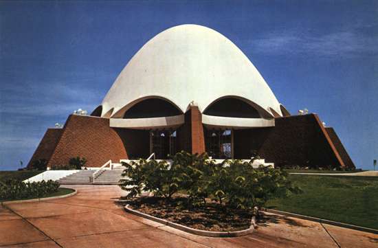
In earlier entries (here and here) I discussed using an inflatable bladder as a form to support masonry units as they are assembled into a dome. It is a simple modification to change a hemispherical bladder into a catenary-shaped bladder which can be used to support block as they are assembled into a catenary dome. A dome with the thinnest walls, using the fewest number of unit shapes, in the strongest possible configuration is provided by using this method.
Friday, February 17, 2012
Tension cables in a masonry dome or sphere
The interlocking triangular block which I’ve developed and refer to as a dimp (dual inverse mirror plane) has a symmetry which allows a clear line-of-sight path along the center of each interlocking abutting edge of the block, as shown below.


This means that cable, or wire, or rope, or any appropriate tensile element can be incorporated into an assembled structure. These cables can be placed on each of the three sides of a given masonry unit and woven together (I ask the reader to forgive my sloppy lines!).

A number of different types of regular polyhedra can be assembled from these triangular interlocking blocks. These configurations can be used as templates for making spheres, or domes, or parts of domes. The polyhedra which can be assembled from the hex and pent blocks include icosahedrons, dodecahedrons, icosidodecahedrons, truncated icosahedrons, and snub dodecahedron, among others.
Icosahedron
Dodecahedron
Icosidodecahedron
Truncated Icosahedron
Snub Dodecahedron
In addition to the different polyhedral arrangements to choose from, different frequencies of these structures can be used to make larger or smaller domes or spheres. Many different sizes of structures can be made from just a couple of unit shape triangular blocks.

As a given polyhedral dome is built, the first triangular blocks are laid on the starter course. The starter course is a circular ring. In between block anchors are cast in the concrete foundation, to which cables are attached. These cables are placed in the abutting edge of the interlocking face and woven into the structure as it is assembled. Shown below is a complete sphere being made, with a few of the cable loops pictured (I didn’t draw them all, it would be too sloppy).

Upon completion a sphere or dome has an interconnecting tensile web of great circle arc cables which hold the structure together. Springs may be incorporated into the cable system to allow movement while also providing a restoring force, which will respond to any deformation by returning the structure to its original round shape. The drawing below shows just some of the great circle arcs described by weaving cable elements into the abutting edges of blocks.

This tensile configuration system is applicable in cases where extreme loading conditions are expected. This includes seismic activity, hurricanes, tornadoes, blast resistant structures, hardened structures, etc.
The combination of a mortarless gasket system (as described in my previous entry) together with a woven tensile cable system creates an efficient, inexpensive, easy to assemble, high performance masonry construction method.
Monday, February 6, 2012
The best masonry unit possible? Really?
I have written many entries on this blog describing a mass-produced triangular interlocking masonry system which I have developed. I have attempted to describe some of the advantages of this system, and provided many examples both of this system being used, and how it could be used in various applications. Today I will attempt to describe how this system represents a mathematical limit: that this system represents the actual limit of this design.


First, we look at a basic question: why use triangular block? To understand this, first we’ll take a look at domes. Domes are sections of spheres. Spheres can be described by subdivision into geometrical shapes. In classical domes, this subdivision is done according to lines of latitude and longitude, so that the shapes are rectangular-ish or square-ish in their general aspect. It becomes immediately obvious that the resulting blocks differ substantially in their size and shape, each from the other.
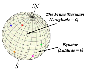
The shapes around the ‘equator’ (or great circle arc) of a sphere are larger than those found at the poles. The blocks from the “polar” area of a sphere cannot fit in the location of the “equatorial” areas, and vice-versa. This means that these blocks must be custom made and precision fit to their individual specific locations in the dome or spherical section. This creates a very large number of individual masonry shapes, and each must be made for its specific location in a structure.
In contrast, there are geometric bodies known as polyhedra, which are assembled from regular repeating unit shapes, each of which are interchangeable. Each of these polyhedron approximates a sphere, or spherical section. The regular geometric shapes which assemble into and constitute a polyhedron are triangles, squares, pentagons hexagons, and a few other polygons. It is critical to note that any polygon with more than three sides can be made into triangles. For example, a pentagon can be assembled from 5 triangles; a hexagon can be assembled from 6 triangles, etc.
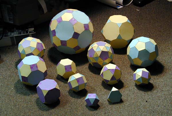
This means that all regular polyhedra can be assembled from triangular shapes. Each of these triangular shapes is interchangeable across the assembled dome or sphere. This is in direct contrast with rectangular or square shapes which lines of latitude and longitude describe on a sphere or spherical section, such as a dome. This means that the number of different shapes is reduced to a bare minimum, and that blocks are interchangeable in a structure. This feature makes for a much easier and greatly simplified method of construction.
Second, we’ll take a look at creating an interlock between blocks. The interlock provides a means of locating the block within the assembled structure: that is, the blocks are kept from sliding or otherwise moving outside the tangential surface of the shell, dome, or sphere. They are locked into radial position. In my last entry I described the importance of this interlocking feature in keeping block located within the tangential curved surface of a dome. If the block are free to slide out of the radial surface, a hinge is created, and the structure can buckle and collapse. The interlocking feature thus makes assembled domes and arches much stronger, since the block are locked into their radial position in a sphere or dome.
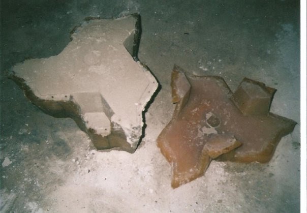
Third, these interlocking triangular block are able to be made on a two-piece mold without an undercut, or draft, or negative angle. This is critical because it allows for the masonry shapes to be inexpensively and rapidly mass-produced. If there is an undercut, or draft, or negative angle, then the unit shapes will not release from a mold: it is stuck and becomes hard to release. A draft angle (or negative angle, or undercut) greatly complicates making the shape. Sliding parts (to release a shape) and complex molds make such a shape uneconomical to produce. It is instructive to note that concrete block are manufactured in matter of mere seconds. To slow this process changes the economics of production, and the product so made is not economically viable. It is critical to provide a simple two-piece mold without any undercuts, as shown below.

Fourth –and finally- the block must be able to be assembled without any draft, or undercut, or negative angle. The masonry shapes must be able to slide into their assembled position. If the structure (dome or sphere) must be “pulled apart” to allow the interlocking feature to engage, the structure cannot be built. It is critical that there is not an undercut, or draft, or negative angle in terms of assembly. For example, the blocks I’ve developed have a half-diamond key with an obtuse angle (at the tip of the key) of 120 degrees. If the key were a half-square, with an angle of 90 degrees at the tip of the key, then there is a draft angle, or undercut, or negative angle which prevents the block from sliding together and being assembled. In the drawing below, if the blocks had square- cornered keys, they could not be assembled; it would create an undercut.

The triangular interlocking masonry system which I’ve developed represents the mathematical limit of such a shape, and it simply cannot be improved upon. If there were more of an interlock, the block would not release from a mold, and simply could not be made. If there were an undercut in terms of assembly, then no structures could be built because the blocks simply couldn’t be assembled.
This was first pointed out to me by a team of mathematicians who attended my thesis defense, when I unveiled this design as part of my fulfillment for my degree in Masonry Science at Alfred University’s New York State College of Ceramics. I am still only beginning to appreciate the significance of this mathematical proof. Within the parameters I described in this entry, it is not possible to improve on this design; it reflects a mathematical and geometric limit of design.
See about the art of limits here. later this same month.
See about the art of limits here. later this same month.
Thursday, April 7, 2011
The worst limerick in the universe
There once was a mason named Pete
whose domes were built as a feat
of triangular block
but others did mock
his work as an igloo concrete.

whose domes were built as a feat
of triangular block
but others did mock
his work as an igloo concrete.

Sunday, July 4, 2010
Evaluating a masonry dome
A friend of mine, Dick Fischbeck, recently shared an article with me about concrete domes built at Yerba Buena Center for the Arts in San Francisco, California. Mr. Fischbeck is a follower of R. Buckminster Fuller, and believes –as Fuller did- that weight is an important criterion for evaluating a building. As I discussed earlier in this blog, if a building weighs too much, it is fundamentally flawed, according to Fuller and his followers. So Mr. Fischbeck sent me this article, writing “here’s a bad idea for you!”
I read this article and was quite intrigued. I had to agree with Dick, that this seemed like a bad idea, although I suspect I have different reasons for thinking so. This is an interesting example which shows many of the advantages of the triangular interlocking masonry system which I’ve been describing on this blog, versus conventional masonry assembled with rectangular bricks and blocks.
At the risk of upsetting this large team of engineers, architects, artists, donors, sponsors, volunteers and anyone else involved in this project, I will now offer my informed critique of this structure. It is my intention to show that a better system is available for masonry construction of domes and spherical sections. Given that Mark Sinclair, a principal at Degenkolb Engineering, which donated expertise and staff time to this project, is quoted as stating "Part of the reason I'm excited is that with something like this, you see how it could be applied (economically) to homes and small commercial buildings," I am gently trying to point out that there is a much better way to build masonry domes than what was done here, and to apply this improved masonry method to the economical construction of homes and small commercial buildings.
First, if we look at the assembled structure built at Yerba Buena, the profile of the dome structure is accentuated by undulations and sharp changes in the radial design it attempts to describe. These undulations create undue and unwanted focal points for stress. At these locations, the stresses become focused and serve as points where failure is more likely to occur. A more stable design is provided if the structure is kept truly radial or catenary, such that there is no focal point for stress.

Michael Ramage, an engineer who attended MIT and is currently teaching at Cambridge University in England, designed this dome system at Yerba Buena. Dr. Ramage is quoted as saying "Vagaries of construction are to be accepted ... We let the structural forces dictate what the forms want to be," in explaining the undulations found in this dome system. To me, these “vagaries” are to be minimized, avoided and are not acceptable. To me, they visually detract from the form, and from an engineering standpoint provide focal areas of stress which weaken the structure. To me, the architect, designer and builder should dictate what the form is, not the vagaries of construction.

Second, a rectangular brick or block is not the ideal unit shape for assembling a dome structure. As discussed earlier in this blog, a triangular block is inherently disposed to conjugate shearing along control joints, so that stress is allowed to be relieved through strain (movement) in a controlled manner; the structure is “pre-fractured” and is thus less likely to suffer a fracture by nature of its being pre-broken.
A rectangular block or brick simply cannot be assembled into a sphere (or dome) without the creation of gaps or spaces between bricks, unless the bricks are custom cut and fitted to their specific location. Conversely, triangular blocks can be assembled into a number of polyhedral arrangements, without creating gaps or spaces between bricks. These triangular unit shapes are interchangeable and do not have to be custom cut or placed at specific locations within a dome or sphere.

If a very large dome is assembled, and mortar is used between bricks, then the effect of gaps or spaces between bricks is minimized. One obvious example of a well-executed dome built with rectangular bricks is the Brunelleschi’s Duomo, which also utilized a herringbone pattern for bricklaying. On a smaller scale (smaller domes, like the Yerba Buena domes), these gaps and spaces between bricks are noticeable, and have an effect on both the visual appearance of a structure and its engineering performance.
The domes assembled at Yerba Buena were done with two concentric shells of brick; one interior and one exterior. Between these shells, a geotextile fabric was included as a tensile element to help provide some tensile reinforcement to the overall structure. To me, this use of geotextile fabric appeared somewhat sloppy, wasteful and inelegant.
 The masonry system I have developed and am attempting to describe on this blog also allows for concentric shells to be assembled, if so desired. Also, the interlocking “DIMP” design allows for a tensile element to be incorporated into the structure, in a more efficient and simple system which involves weaving this tensile element into the blocks as they are assembled. This incorporation of tensile elements is done so that the tensile elements are placed at the conjugate shear planes within the structure, resulting in a stronger, tougher system which utilizes active control joints, allowing for stress (applied force) to be relieved via strain (movement).
This notion of allowing stress to be relieved by strain figures critically into another aspect of evaluating masonry domes regarding seismic stresses. In the Yerba Buena structure, the architects, engineers and designers had to design the structure so that it was suitable for earthquakes which are more likely to occur at this location. Their design dealt with this engineering challenge by providing a rigid dome, which will move as a whole, atop a base isolation system. If the ground were to move underneath the dome, the whole dome is free to move in its entirety; like an upside down bowl placed atop ball bearings. This engineering solution requires an expensive and extensive base isolation mechanism which the structure sits on top of. In contrast, the interlocking triangular block system I’ve been describing in this blog relies on the ability to deform (strain) under seismic forces (stress). This is possible through both the interlocking feature of the block and tensile elements (steel cable, carbon fiber, etc.) woven into the block as they are assembled. Each tensile element is anchored at the base of the dome, and fitted with a spring which dampens the stresses and add to the dynamic flexibility of the dome. Thus the Yerba Buena domes and the domes I’ve developed have fundamentally different approaches to dealing with seismic stresses. They rely on the entire dome being able to move relative to the ground, and my design relies on the ability of the structure to strain along control joints, via conjugate shearing. The design I’ve developed is further advantageous because a dome thus constructed can sit atop vertical walls, and is still free to move; the Yerba Buena dome cannot be built atop vertical walls, unless the entire structure (including vertical walls) is allowed to move via a base isolation system. Again, this requires more extensive and expensive engineering features.
The Yerba Buena dome used lightweight bricks for their construction. This seemed to me an unnecessary feature. With concrete bricks, any reduction in weight is also accompanied by a reduction in strength. One of the fundamental features of a masonry dome is its high compressive strength: there is really no reason to use a lightweight block, unless one is a strict adherent to the principals of Bucky Fuller. It seems to me that this structure was made less strong by using lightweight bricks. The only real advantage to lightweight bricks is that they serve as better thermal insulators. However, this occurs at the loss of thermal mass to the structure, which is a beneficial aspect of masonry construction. I believe (as do others) that a more thermally efficient structure is provided by incorporating a high thermal mass, and simply insulating the outside of the structure so as to maximize the thermal mass benefits.
It should be noted that lightweight masonry units are in fact advantageous for high temperature refractory applications, where thermal insulation benefits outweigh the thermal mass benefits at high operating temperatures, such as in a kiln or furnace. The kilns and furnaces I’ve built using my masonry system did incorporate liquid foam insulation into the cast bricks, to provide a lightweight insulating brick.
If a dome were built with standard manufactured rectangular concrete block, the dome would have the block oriented such that the weak axis of compressive strength is facing the outside, or radial, direction (the weak axis is normal to the axis of compression as the block are made). The triangular concrete block which I’ve developed have the high strength axis (direction of concrete compaction and consolidation during manufacture) facing the outside. This provides a much stronger structure.
This wraps up my evaluation of the Yerba Buena dome system. It is my hope that anyone reading this critique can do so in the constructive manner in which it was intended. I am certainly very happy to see others attempting to build concrete domes today, and to aspire to creative solutions to some challenging engineering problems. If anyone wants to try and build a better concrete masonry dome, please contact me; I may be able to help. I am willing to allow use of my patented systems at no cost for interesting and worthy projects such as this.
Construction is a conservative industry. Within construction, the field of masonry is even more conservative. I hope to advance the state of masonry today, through a thoughtful approach, using good design and appropriate use of materials.
I read this article and was quite intrigued. I had to agree with Dick, that this seemed like a bad idea, although I suspect I have different reasons for thinking so. This is an interesting example which shows many of the advantages of the triangular interlocking masonry system which I’ve been describing on this blog, versus conventional masonry assembled with rectangular bricks and blocks.
At the risk of upsetting this large team of engineers, architects, artists, donors, sponsors, volunteers and anyone else involved in this project, I will now offer my informed critique of this structure. It is my intention to show that a better system is available for masonry construction of domes and spherical sections. Given that Mark Sinclair, a principal at Degenkolb Engineering, which donated expertise and staff time to this project, is quoted as stating "Part of the reason I'm excited is that with something like this, you see how it could be applied (economically) to homes and small commercial buildings," I am gently trying to point out that there is a much better way to build masonry domes than what was done here, and to apply this improved masonry method to the economical construction of homes and small commercial buildings.
First, if we look at the assembled structure built at Yerba Buena, the profile of the dome structure is accentuated by undulations and sharp changes in the radial design it attempts to describe. These undulations create undue and unwanted focal points for stress. At these locations, the stresses become focused and serve as points where failure is more likely to occur. A more stable design is provided if the structure is kept truly radial or catenary, such that there is no focal point for stress.

Michael Ramage, an engineer who attended MIT and is currently teaching at Cambridge University in England, designed this dome system at Yerba Buena. Dr. Ramage is quoted as saying "Vagaries of construction are to be accepted ... We let the structural forces dictate what the forms want to be," in explaining the undulations found in this dome system. To me, these “vagaries” are to be minimized, avoided and are not acceptable. To me, they visually detract from the form, and from an engineering standpoint provide focal areas of stress which weaken the structure. To me, the architect, designer and builder should dictate what the form is, not the vagaries of construction.

Second, a rectangular brick or block is not the ideal unit shape for assembling a dome structure. As discussed earlier in this blog, a triangular block is inherently disposed to conjugate shearing along control joints, so that stress is allowed to be relieved through strain (movement) in a controlled manner; the structure is “pre-fractured” and is thus less likely to suffer a fracture by nature of its being pre-broken.
A rectangular block or brick simply cannot be assembled into a sphere (or dome) without the creation of gaps or spaces between bricks, unless the bricks are custom cut and fitted to their specific location. Conversely, triangular blocks can be assembled into a number of polyhedral arrangements, without creating gaps or spaces between bricks. These triangular unit shapes are interchangeable and do not have to be custom cut or placed at specific locations within a dome or sphere.

If a very large dome is assembled, and mortar is used between bricks, then the effect of gaps or spaces between bricks is minimized. One obvious example of a well-executed dome built with rectangular bricks is the Brunelleschi’s Duomo, which also utilized a herringbone pattern for bricklaying. On a smaller scale (smaller domes, like the Yerba Buena domes), these gaps and spaces between bricks are noticeable, and have an effect on both the visual appearance of a structure and its engineering performance.
The domes assembled at Yerba Buena were done with two concentric shells of brick; one interior and one exterior. Between these shells, a geotextile fabric was included as a tensile element to help provide some tensile reinforcement to the overall structure. To me, this use of geotextile fabric appeared somewhat sloppy, wasteful and inelegant.

This notion of allowing stress to be relieved by strain figures critically into another aspect of evaluating masonry domes regarding seismic stresses. In the Yerba Buena structure, the architects, engineers and designers had to design the structure so that it was suitable for earthquakes which are more likely to occur at this location. Their design dealt with this engineering challenge by providing a rigid dome, which will move as a whole, atop a base isolation system. If the ground were to move underneath the dome, the whole dome is free to move in its entirety; like an upside down bowl placed atop ball bearings. This engineering solution requires an expensive and extensive base isolation mechanism which the structure sits on top of. In contrast, the interlocking triangular block system I’ve been describing in this blog relies on the ability to deform (strain) under seismic forces (stress). This is possible through both the interlocking feature of the block and tensile elements (steel cable, carbon fiber, etc.) woven into the block as they are assembled. Each tensile element is anchored at the base of the dome, and fitted with a spring which dampens the stresses and add to the dynamic flexibility of the dome. Thus the Yerba Buena domes and the domes I’ve developed have fundamentally different approaches to dealing with seismic stresses. They rely on the entire dome being able to move relative to the ground, and my design relies on the ability of the structure to strain along control joints, via conjugate shearing. The design I’ve developed is further advantageous because a dome thus constructed can sit atop vertical walls, and is still free to move; the Yerba Buena dome cannot be built atop vertical walls, unless the entire structure (including vertical walls) is allowed to move via a base isolation system. Again, this requires more extensive and expensive engineering features.
The Yerba Buena dome used lightweight bricks for their construction. This seemed to me an unnecessary feature. With concrete bricks, any reduction in weight is also accompanied by a reduction in strength. One of the fundamental features of a masonry dome is its high compressive strength: there is really no reason to use a lightweight block, unless one is a strict adherent to the principals of Bucky Fuller. It seems to me that this structure was made less strong by using lightweight bricks. The only real advantage to lightweight bricks is that they serve as better thermal insulators. However, this occurs at the loss of thermal mass to the structure, which is a beneficial aspect of masonry construction. I believe (as do others) that a more thermally efficient structure is provided by incorporating a high thermal mass, and simply insulating the outside of the structure so as to maximize the thermal mass benefits.
It should be noted that lightweight masonry units are in fact advantageous for high temperature refractory applications, where thermal insulation benefits outweigh the thermal mass benefits at high operating temperatures, such as in a kiln or furnace. The kilns and furnaces I’ve built using my masonry system did incorporate liquid foam insulation into the cast bricks, to provide a lightweight insulating brick.
If a dome were built with standard manufactured rectangular concrete block, the dome would have the block oriented such that the weak axis of compressive strength is facing the outside, or radial, direction (the weak axis is normal to the axis of compression as the block are made). The triangular concrete block which I’ve developed have the high strength axis (direction of concrete compaction and consolidation during manufacture) facing the outside. This provides a much stronger structure.
This wraps up my evaluation of the Yerba Buena dome system. It is my hope that anyone reading this critique can do so in the constructive manner in which it was intended. I am certainly very happy to see others attempting to build concrete domes today, and to aspire to creative solutions to some challenging engineering problems. If anyone wants to try and build a better concrete masonry dome, please contact me; I may be able to help. I am willing to allow use of my patented systems at no cost for interesting and worthy projects such as this.
Construction is a conservative industry. Within construction, the field of masonry is even more conservative. I hope to advance the state of masonry today, through a thoughtful approach, using good design and appropriate use of materials.
Thursday, May 27, 2010
Hot Fluid Catalytic Beds
Hot fluid catalytic beds are used by industry to chemically process materials through heat, combustion and catalysis. One of the largest applications for hot fluid catalytic beds is by the fossil fuel industry, as employed by refineries which process crude oil into its component parts; from gasoline, kerosene, diesel, tar, to petroleum jelly, etc. Fluid Catalytic Cracking (FCC) is the dominant conversion process in petroleum refineries and the major contributor to “value added” in the refining process. Hot fluid catalytic beds are also used for creating fertilizers, cements and many other types of chemicals.
Here is a schematic image of a fluid bed used for cement production:

Here is a decent discussion of ‘cracking’, catalysis and fluid processes:
“The term “cracking” refers to the process through which large hydrocarbon molecules are split into smaller ones in order to obtain lighter hydrocarbons. This process requires very high temperatures and sometimes the use of a “catalyst”. In fact, there are different types of cracking. There are two types of cracking which have additional variations in the way they are implemented.
The first type of cracking is called “Thermal cracking”. It basically consists in heating the hydrocarbons until they reach high temperatures using also high pressures in some cases. This allows the hydrocarbons to break apart forming simpler hydrocarbons. The simple word “cracking” is often used to refer to this type of cracking as this is the oldest and most common type of cracking. However, thermal cracking can be achieved in different ways. There are three methods to implement thermal cracking:
• Steam - high temperature steam (1500 degrees Fahrenheit / 816 degrees Celsius) is used to break ethane, butane and naptha into ethylene and benzene, which are used to manufacture chemicals.
• Visbreaking - residual from the distillation tower is heated (900 degrees Fahrenheit / 482 degrees Celsius), cooled with gas oil and rapidly burned (flashed) in a distillation tower. This process reduces the viscosity of heavy weight oils and produces tar.
• Coking - residual from the distillation tower is heated to temperatures above 900 degrees Fahrenheit / 482 degrees Celsius until it cracks into heavy oil, gasoline and naphtha. When the process is done, a heavy, almost pure carbon residue is left (coke); the coke is cleaned from the cokers and sold.
The second type of cracking is called “Catalytic cracking” and it uses a catalyst to separate different hydrocarbons. This method of cracking generally uses zeolites as catalysts. Catalytic cracking can be also done through other catalyst such as aluminum hydrosilicate, bauxite and silica-alumina. As in the case of thermal cracking there are different methods to implement catalytic cracking:
• Fluid catalytic cracking- a hot, fluid catalyst (1000 degrees Fahrenheit / 538 degrees Celsius) cracks heavy gas oil into diesel oils and gasoline.
• Hydrocracking- similar to fluid catalytic cracking, but uses a different catalyst, lower temperatures, higher pressure, and hydrogen gas. It takes heavy oil and cracks it into gasoline and kerosene (jet fuel). Hydrocracking is basically a refining process that uses hydrogen and catalysts with relatively low temperatures and high pressures for converting middle boiling or residual material to high-octane gasoline, reformer charge stock, jet fuel, and/or high grade fuel oil. The process uses one or more catalysts, depending upon product output.
Once hydrocarbons have been cracked into smaller ones they pass through another fractional distillation column to be further distilled and to separate different components inside them.”
Here is a fluidized bed schematic for blast furnace metal production:
 Catalysts are typically placed on an inert, chemically stable, refractory material. This is typically ceramic. Before the invention of the masonry system described here on this blog, these catalytic domes were made of custom ceramic parts which were precision fit to a specific location within a dome. This is time consuming and expensive.
Here's a photograph of the outside of a hot fluid catalytic bed reactor:

The masonry system I’ve been describing is ideal for applications such as hot fluid catalytic beds. All masonry units are interchangeable, they do not have to be custom cut, they do not have to be precision fit, and are much easier to assemble. Each masonry unit can be made with a through hole, to allow for hot gas to flow through the dome. Alternatively, the masonry units can be made of porous material, so that hot gas can also flow through the dome. Finally, the “dome” can be flipped upside-down, like a bowl. This is advantageous because in a dome the gas flow tends to be higher in the center of the dome; gas flow should ideally be equal across the surface of the dome, and inverted bowl helps to achieve this sort of flow.
This masonry system provides an improved method for constructing hot fluid catalytic beds for use in several fields of chemical processing industries.
Here is a schematic image of a fluid bed used for cement production:

Here is a decent discussion of ‘cracking’, catalysis and fluid processes:
“The term “cracking” refers to the process through which large hydrocarbon molecules are split into smaller ones in order to obtain lighter hydrocarbons. This process requires very high temperatures and sometimes the use of a “catalyst”. In fact, there are different types of cracking. There are two types of cracking which have additional variations in the way they are implemented.
The first type of cracking is called “Thermal cracking”. It basically consists in heating the hydrocarbons until they reach high temperatures using also high pressures in some cases. This allows the hydrocarbons to break apart forming simpler hydrocarbons. The simple word “cracking” is often used to refer to this type of cracking as this is the oldest and most common type of cracking. However, thermal cracking can be achieved in different ways. There are three methods to implement thermal cracking:
• Steam - high temperature steam (1500 degrees Fahrenheit / 816 degrees Celsius) is used to break ethane, butane and naptha into ethylene and benzene, which are used to manufacture chemicals.
• Visbreaking - residual from the distillation tower is heated (900 degrees Fahrenheit / 482 degrees Celsius), cooled with gas oil and rapidly burned (flashed) in a distillation tower. This process reduces the viscosity of heavy weight oils and produces tar.
• Coking - residual from the distillation tower is heated to temperatures above 900 degrees Fahrenheit / 482 degrees Celsius until it cracks into heavy oil, gasoline and naphtha. When the process is done, a heavy, almost pure carbon residue is left (coke); the coke is cleaned from the cokers and sold.
The second type of cracking is called “Catalytic cracking” and it uses a catalyst to separate different hydrocarbons. This method of cracking generally uses zeolites as catalysts. Catalytic cracking can be also done through other catalyst such as aluminum hydrosilicate, bauxite and silica-alumina. As in the case of thermal cracking there are different methods to implement catalytic cracking:
• Fluid catalytic cracking- a hot, fluid catalyst (1000 degrees Fahrenheit / 538 degrees Celsius) cracks heavy gas oil into diesel oils and gasoline.
• Hydrocracking- similar to fluid catalytic cracking, but uses a different catalyst, lower temperatures, higher pressure, and hydrogen gas. It takes heavy oil and cracks it into gasoline and kerosene (jet fuel). Hydrocracking is basically a refining process that uses hydrogen and catalysts with relatively low temperatures and high pressures for converting middle boiling or residual material to high-octane gasoline, reformer charge stock, jet fuel, and/or high grade fuel oil. The process uses one or more catalysts, depending upon product output.
Once hydrocarbons have been cracked into smaller ones they pass through another fractional distillation column to be further distilled and to separate different components inside them.”
Here is a fluidized bed schematic for blast furnace metal production:

Here's a photograph of the outside of a hot fluid catalytic bed reactor:

The masonry system I’ve been describing is ideal for applications such as hot fluid catalytic beds. All masonry units are interchangeable, they do not have to be custom cut, they do not have to be precision fit, and are much easier to assemble. Each masonry unit can be made with a through hole, to allow for hot gas to flow through the dome. Alternatively, the masonry units can be made of porous material, so that hot gas can also flow through the dome. Finally, the “dome” can be flipped upside-down, like a bowl. This is advantageous because in a dome the gas flow tends to be higher in the center of the dome; gas flow should ideally be equal across the surface of the dome, and inverted bowl helps to achieve this sort of flow.
This masonry system provides an improved method for constructing hot fluid catalytic beds for use in several fields of chemical processing industries.
Wednesday, May 12, 2010
E.T., Dome Home!
The masonry system I’ve been describing is appropriate for building structures on the moon, other planets, and in space. This is what we’ll be looking at today.

The cost of sending any material into orbit is very high. Currently this cost is estimated at around $5,000 per pound, according to PhysOrg. If we can send less material into orbit, and instead use the materials found in space, we can greatly reduce the cost of our missions in space.
The moon has long been considered a potential base for deep space exploration. This is because the cost of leaving lunar orbit is a small fraction of the cost of leaving earth orbit; it takes a lot less energy to launch from the moon (less than 5%). Currently NASA plans to have a habitable moon base by 2024; although this plan is currently being brought under scrutiny by the Obama administration.
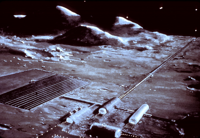
The surface of the moon is comprised of a mix of rocks, minerals and clays not entirely unlike earth. It would be possible to make masonry units from the rock and mineral mixes found on the moon. This material could be surface mined, mixed, and formed into blocks by robotic equipment. Here is an artist’s conception of lunar mining.

The block system described on this blog would lend itself readily to robotic production, due to the simple two-piece mold and ease of production. Once formed, these blocks could be fired (heat treated) by a solar kiln, where mirrors reflect and focus solar energy to provide sintering and solidification to masonry units. Alternatively, a small addition of cement-like material could help consolidate and form these blocks.
Robots could then be used to assemble a structure on the surface of the moon. The interlocking feature, together with a woven tensile element, provides a relatively simple assembly method with a robust design and high strength. A spherical section (e.g., dome) would be an ideal configuration for a lunar structure.
Once assembled, the dome would be lined with a bladder and inflated to provide a habitable structure prior to human arrival. The mineral composition of the lunar surface provides an appropriate material to block out cosmic radiation and harmful high energy particles. The high specific heat and thermal mass of this structure would greatly dampen the extreme temperature swings which occur between lunar day and night. The effects of extreme hot and extreme cold would be greatly reduced.
The unprecedented success of the robotic systems on the recent Mars Rover missions indicates that robotic units are capable of performing adequately when asked to perform rather sophisticated maneuvers and manipulations. Honeybee Robotics was involved in developing and deploying these robotic systems on the Mars missions. I have begun preliminary conversations with their engineers on my approach, they seem interested.
Aside from the moon and a similar sort of deployment on Mars, this masonry system could also be used to build self-contained satellites as complete spheres. These could be made for near earth orbit, for “way stations” throughout our solar system, to store material such as fuel, water and oxygen. They could also be placed on larger asteroids in the asteroid belt, such as 253 Mathilde.
This masonry system provides a compelling set of reasons for its deployment in extraterrestrial applications. First, we greatly reduce the cost of sending material into orbit from earth. Secondly, it can be made using the materials found on the moon, Mars, etc. Third, it can be produced and assembled robotically. Finally, this system blocks out harmful cosmic radiation, takes advantage of the high thermal mass to dampen out extreme temperature fluctuations, and provides an appropriate architectural shell for housing a bladder, to provide a suitable atmosphere for human habitation.
Next time we’ll take a look at retaining walls and landscaping applications for this block system. This is a very large and growing market for masonry units.

The cost of sending any material into orbit is very high. Currently this cost is estimated at around $5,000 per pound, according to PhysOrg. If we can send less material into orbit, and instead use the materials found in space, we can greatly reduce the cost of our missions in space.
The moon has long been considered a potential base for deep space exploration. This is because the cost of leaving lunar orbit is a small fraction of the cost of leaving earth orbit; it takes a lot less energy to launch from the moon (less than 5%). Currently NASA plans to have a habitable moon base by 2024; although this plan is currently being brought under scrutiny by the Obama administration.
The surface of the moon is comprised of a mix of rocks, minerals and clays not entirely unlike earth. It would be possible to make masonry units from the rock and mineral mixes found on the moon. This material could be surface mined, mixed, and formed into blocks by robotic equipment. Here is an artist’s conception of lunar mining.
The block system described on this blog would lend itself readily to robotic production, due to the simple two-piece mold and ease of production. Once formed, these blocks could be fired (heat treated) by a solar kiln, where mirrors reflect and focus solar energy to provide sintering and solidification to masonry units. Alternatively, a small addition of cement-like material could help consolidate and form these blocks.
Robots could then be used to assemble a structure on the surface of the moon. The interlocking feature, together with a woven tensile element, provides a relatively simple assembly method with a robust design and high strength. A spherical section (e.g., dome) would be an ideal configuration for a lunar structure.
Once assembled, the dome would be lined with a bladder and inflated to provide a habitable structure prior to human arrival. The mineral composition of the lunar surface provides an appropriate material to block out cosmic radiation and harmful high energy particles. The high specific heat and thermal mass of this structure would greatly dampen the extreme temperature swings which occur between lunar day and night. The effects of extreme hot and extreme cold would be greatly reduced.
The unprecedented success of the robotic systems on the recent Mars Rover missions indicates that robotic units are capable of performing adequately when asked to perform rather sophisticated maneuvers and manipulations. Honeybee Robotics was involved in developing and deploying these robotic systems on the Mars missions. I have begun preliminary conversations with their engineers on my approach, they seem interested.
Aside from the moon and a similar sort of deployment on Mars, this masonry system could also be used to build self-contained satellites as complete spheres. These could be made for near earth orbit, for “way stations” throughout our solar system, to store material such as fuel, water and oxygen. They could also be placed on larger asteroids in the asteroid belt, such as 253 Mathilde.
This masonry system provides a compelling set of reasons for its deployment in extraterrestrial applications. First, we greatly reduce the cost of sending material into orbit from earth. Secondly, it can be made using the materials found on the moon, Mars, etc. Third, it can be produced and assembled robotically. Finally, this system blocks out harmful cosmic radiation, takes advantage of the high thermal mass to dampen out extreme temperature fluctuations, and provides an appropriate architectural shell for housing a bladder, to provide a suitable atmosphere for human habitation.
Next time we’ll take a look at retaining walls and landscaping applications for this block system. This is a very large and growing market for masonry units.
Friday, April 2, 2010
Cylinders and arches from triangular block
So far we’ve looked at triangular interlocking masonry units which can be used to assemble into a sphere or part of a sphere, such as a dome.
This masonry system also uses interlocking triangular masonry units to build cylinders, parts of cylinders and straight walls. Cylinder sections can be used to build arches for roofs, serpentine arrangements, straight walls and any combination of these elements.
There are two types of triangular blocks needed to assemble into a cylinder. One of them is referred to as a “flat” block, because the top of the block gets ‘cut off’ or truncated, creating a flat top. The second type of block is referred to as a ‘par’ block, because the abutting edges are parallelograms. Both of these cylinder blocks lend themselves readily to the independent diamond-shaped key configuration, or the ‘simp’ (single inverse mirror plane) or ‘dimp’ (double inverse mirror plane) which I described earlier in this blog.
Here are some illustrations of the ‘flat’ block, shown with a ‘simp’ configuration.


Here are some illustrations of the ‘par’ block, also shown with a ‘simp’ configuration.


Shown below are two views of a cylinder section made using the 'flat' and 'par' blocks. One beneficial aspect of this design is that there are 'ribs' or corrugated rings going around the cylinder. This makes the structure much stronger, and increase flexural rigidity, much like the ribs on a tin can.

 Taken in its entirety, the cylinder, arch, straight wall, sphere and dome arrangements provide extensive design flexibility for this masonry system. All the benefits of this system apply to all these embodiments. These blocks can be mass-produced, they interlock, they bear loads under compression, the abutting faces are comprised of conjugate shearing, they can be woven together using tensile elements; this is a robust and high strength system which can be produced at a very low cost. There are many ways to configure this system, a few possibilities are shown below:

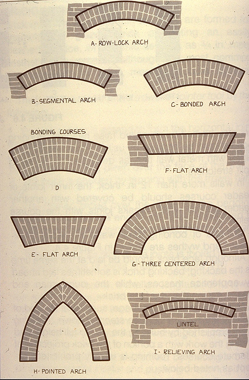
Here are some illustrations showing different types of masonry arches. Each of these configurations is made from sections of cylinders. Triangular cylinder blocks can be used to build each of these types of arches. This system has extensive design flexibility and can be used to create some beautiful architecture.
An interesting aspect of human architecture is the convention of square walls and square corners in buildings. This is almost a universal convention, found in different cultures across the globe. People are somehow comforted and ‘used’ to square walls and square corners. Is it possible to build arched roofs from triangular blocks that will fit on top of square or rectangular structures? We’ll take a look at this very interesting design problem next time.
This masonry system also uses interlocking triangular masonry units to build cylinders, parts of cylinders and straight walls. Cylinder sections can be used to build arches for roofs, serpentine arrangements, straight walls and any combination of these elements.
There are two types of triangular blocks needed to assemble into a cylinder. One of them is referred to as a “flat” block, because the top of the block gets ‘cut off’ or truncated, creating a flat top. The second type of block is referred to as a ‘par’ block, because the abutting edges are parallelograms. Both of these cylinder blocks lend themselves readily to the independent diamond-shaped key configuration, or the ‘simp’ (single inverse mirror plane) or ‘dimp’ (double inverse mirror plane) which I described earlier in this blog.
Here are some illustrations of the ‘flat’ block, shown with a ‘simp’ configuration.
Here are some illustrations of the ‘par’ block, also shown with a ‘simp’ configuration.
Shown below are two views of a cylinder section made using the 'flat' and 'par' blocks. One beneficial aspect of this design is that there are 'ribs' or corrugated rings going around the cylinder. This makes the structure much stronger, and increase flexural rigidity, much like the ribs on a tin can.
Here are some illustrations showing different types of masonry arches. Each of these configurations is made from sections of cylinders. Triangular cylinder blocks can be used to build each of these types of arches. This system has extensive design flexibility and can be used to create some beautiful architecture.
An interesting aspect of human architecture is the convention of square walls and square corners in buildings. This is almost a universal convention, found in different cultures across the globe. People are somehow comforted and ‘used’ to square walls and square corners. Is it possible to build arched roofs from triangular blocks that will fit on top of square or rectangular structures? We’ll take a look at this very interesting design problem next time.
Thursday, March 11, 2010
Introduction

I'm a masonry designer developing novel masonry systems for new applications. This blog will describe what my ideas are, how I'm making them, various uses, and so on. I will share ideas and hope to get feedback from as many interested people as I can.
I'm especially interested in doing more with concrete block than is currently possible. I want to expand the architectural vocabulary of concrete block construction to include much more than straight vertical walls and square corners. This is pretty much the status quo with current block design and construction.
As a child I had the good fortune of seeing some of the great cathedrals of Europe. This experience left an indelible impression on me. It's probably why I do what I do; masonry architecture can be so much more than rectangular block and vertical walls. Arch, cylinder, dome and sphere should all be part of the masonry repertoire. This is possible with block manufacturing methods and materials, through innovative design.
This is an exciting realm that combines ages-old building techniques with current scientific engineering knowledge and high-efficiency production methods.
Subscribe to:
Posts (Atom)