Thursday, August 11, 2011

Arches at Ninety Degrees

Back in 2000, I had an insight into vaulted arches.  I had been developing triangular interlocking block as a masonry system, and had devised of a method for making cylinders from these triangular blocks.

A cylindrical section can be turned horizontally to create a vaulted arch, like a roman or circular or barrel vault.  

People are largely used to living in a square-cornered building or house.  There is something fundamental to the human psyche that looks to straight walls and square corners within a living space as a standard which sets people at ease.  Domes and round buildings make up a tiny fraction of habitable structures: almost all buildings have straight walls and square corners.  As you read this now, look around you at the building you are in.  I'd be willing to bet that it has straight walls and square corners.  If not, you are in a very tiny minority, living in an "alternative" structure.

It is a challenge to make a vaulted arch roof system sit atop a square cornered building.  In my own masonry approach, which uses triangular block to assemble a cylinder or arch, the triangles can be assembled to provide a helical or spiral edge.  A helix or spiral has translation and rotation, and the 'helicity' or angle of 'spiralness' can be varied.  Think of stretching a slinky: the spiral angle of translation and rotation can be varied, from shallow to steep angles of helicity.

If the translation versus rotation of a given cylindrical section is equal to the radius of the cylinder versus 90 degrees, then this helicicty can be placed atop a right-angled base.  It is thus possible to place vaulted arches atop a right-angled structure.  The right angle can be a "turn-in" as shown below, where the angle between walls is simply 90 degrees, as shown below. (taken from one of my patents)


Below is shown a structure where the vaulted arches are shown as a "turn out" where the walls meet at 270 degrees.  In the case of both a "turn-in" and a "turn-out" a gap is created between the helical edges of the abutting arches where they meet at a corner.  This gap is satisfied by a larger spherical section.  Specifically, if the arches are taken as having a raius of 1.0, then the larger spherical section that fills the gap has a radius of 1.5  (If you'd like to see these images better, just click on them to see a larger view).
This sort of arrangement provides extensive design flexibility.  One, two, three or four vaulted arches can meet at right angles to each other, merging seamlessly into a larger dome or spherical section.

This arrangement creates some very interesting possibilities far outside the realm of masonry.  Could this arrangement have something to do with the structure of DNA and the "magic" of reproduction?  We'll take a look at this next time, including a discussion of centromeres and telomeres.

Tuesday, August 9, 2011

brick & mortar


“Brick & mortar” has come to mean a real, built thing; as opposed to a virtual or digital thing.

Masonry is real, it is meant to last over time.  Masonry construction reflects a confidence in the future.  It is not temporary.
Markets rise and fall; sometimes dramatically.  This is temporary.

Planning for masonry construction during such times displays confidence in a real outcome with an actual brick & mortar result.  In today’s economy, long term thinking and planning are often at odds with quarterly results.

Those with foresight have chosen masonry construction throughout history.  We are left with testament to their optimism with everything from the Pantheon to the Brooklyn Bridge; the Hagia Sophia and Notre Dame Cathedral, all brick & mortar. 

Monday, July 18, 2011

Air supports masonry?

Air is one of the lightest materials, whereas masonry is one of the densest.   It seems improbable that air can be effectively used to support and enforce masonry.  But that’s what I’m looking at today.
A number of innovative approaches to using air as a structural support member have been developed and introduced over the past decade or so.  Some of the most intriguing of these applications involve bridges.

For example, textile composites are used as a framework for inflatable structures.  As discussed here, these inflatable elements are used to provide arches in a concrete bridge.  The arches are made of a membrane inflated with air which serves as a support form or scaffolding while the concrete bridge is constructed.   This approach means that no rebar is necessary; no wooden formwork or other difficult, expensive scaffolding material is required.  The inflated tubes shown above are treated with resin and solidified, then filled with concrete.  These cast curved tubes (or toroidal sections) of concrete are especially ductile, yet very strong.
A number of approaches have been used to provide high-strength inflatable bridges, such as those shown below:


There is an elegant simplicity to using an inflatable element as scaffolding for massive masonry structures.    An inflated surface, or bubble, represents a least energy surface.  There is a balance between the force of the inflated –or pressurized- air, and the tensile strength of the membrane, or “bubble”.  This balance results in a least energy surface.

The simplest of these surfaces is a simple round sphere.  These surfaces can also be tubes, cylinders, and combinations of these elements.  As we look at more complex shapes, we quickly enter the mathematician’s and geometer’s realm of topography.  There are saddle shapes, ‘monkey saddles,” parabolic and hyperbolic curves, even catenary configurations.  Each of these represents a least energy surface.


I am currently experimenting with an inflatable bladder to be used as scaffolding for constructing a masonry sphere.  I am assembling a rubber sphere, which is configured like a ‘beach ball.’   This will be used to assemble masonry spheres below ground, for water storage tanks, septic tanks, and other similar applications; around 8 feet in diameter.  For this use, the sphere will be inflated to a relatively low pressure (~20 psi) and will support block as they are laid.  Once the sphere is complete, the inflatable bladder is deflated and removed.  It is incredible (to me, at least) how much weight a relatively low air pressure can support.  25 psi can hold up tons of block!
Although my test sphere will be relatively small, it will be scale-able.  If the proportions remain intact, then a much larger sphere can be made using the same approach.  As discussed earlier, Galileo tried to impose his square cube law on masonry structures, and he was WRONG, the ancient masons had it right:  scale-ability is one of the defining features of masonry design.  The same system used to build an 8 foot diameter sphere can also be used to build an 80 foot (or 800 foot!) diameter sphere.


Other dome manufacturers use inflatable bladders for their systems; notably Monolithic Domes, as I discussed earlier, here.  Their use is for spraying shotcrete though, not for support and assembly of masonry construction.

As I use my inflatable bladder for masonry scaffolding I’ll post updates and pictures on this blog.  In the past I’ve used wooden scaffolding, I expect this to be much, much easier, faster, safer and cheaper.

Wednesday, June 22, 2011

Particle size distribution of Crickcrete

If we consider concrete, the main ingredient is aggregate:  rocks, stones and sand.  I briefly discussed this here on this blog.

Of real importance is the particle size distribution in the aggregate mix.  The goal in good concrete is to get a complete space filling by using different sized particles.
Aggregate (stones, rocks and sand) is generally not spherical, but has a longer dimension and a shorter dimension.  This results in a “tip” which is located at the ends of the longer dimension, and a “face” which is located at the end of the shorter dimension.  One of the keys to good concrete is tip-to-face contact between larger aggregate.

One of the other keys to good concrete is that the gaps between large aggregate are filled with smaller aggregate, so that there are not empty spaces, or gaps, or interstitial sites between aggregate.  This is what is meant by “space filling.”

There is a field of science which concerns itself with space filling between particles.  My own exposure to this science came in studying ceramics, wherein scientists are typically looking at very small particles.  One of  the insights into space-filling came about in 1930, and was proposed by two scientists (A.E.R. Westman and H.R. Hugill) who worked together to develop a diagram which represented space filling as a percentage of volume based on different sized particles, and is known as a Westman-Hugill diagram.

Here is a quote from an abstract of their paper “The Packing of Particles” published by the Journal of the American Ceramic Society, June 12, 1930: “It is axiomatic that the mode of packing of very large volumes of particles of uniform shape and size is independent of the size of the particles, provided they are large enough for the effect of electrostatic forces, air films, etc., to be negligible. An apparatus is described, in which equal true volumes of approximately spherical particles, ranging in diameter from 0.2 to 0.0035 inch, pack practically to the same apparent volume. This apparatus was used in studying the packing of mixtures of two and three sues of particles. By plotting the data so obtained in diagrams of a particularly convenient character, it is shown that the apparent volumes of mixtures containing unit real volume of solid fall between limiting values which can be calculated from simple assumptions, and that their deviation from these limits depends in a definite manner upon the diameter ratios of the component particles. The conditions governing the application of the results of the study to ceramic technology are pointed out.”

While Westman and Hugill were considering spherical particles for their model, the basic ideas hold for irregular shapes, which is what one encounters in concrete mix.

Here is what I find interesting about this whole concept.  If you go outside and scoop up a shovel full of rocky, sandy mix (not soil, but aggregate, such as one finds in a stream or creek bed) then the mix is very close to the ideal particle size distribution one would design if starting from “scratch.”

I find this incredible!  Nature has provided us with a close to ideal particle size distribution for very good concrete.  Almost everyone fails to appreciate this fact.  Everything we make from concrete would be much more difficult to make if this were not the case.  If we lived in a world of only tiny sand, we would be making large rocks to provide large aggregate.  If we lived in a world of only large rocks, we would be making sand (at a huge cost of time and energy).  As it is, nature has provided us with a very close to ideal concrete mix in terms of aggregate particle size distribution.

There is a commercial brand of concrete known as “quikcrete” which is sold in dry bags.  Friends of mine who are aware that a creek bed provides an ideal mix of aggregate particle size also live in the country, where a creek is known as a “crick”.  They call their homemade concrete “crickcrete” and chuckle and guffaw like country bumpkins.

So grab a shovel, head to the creek and make some of nature’s own crickcrete.

Friday, June 17, 2011

Water storage tanks


I am completing a unique small masonry project.  This is to be a sub-surface water storage tank, made from triangular manufactured concrete block.  I will be using it as a “plunging tank” to cool off after taking a sauna.

This simple prototype uses an early version of the triangular block system described on this blog (here, here and here).  The blocks used for this tank do not utilize the interlocking key and keyway system.  I was just using up some of my older block.

This tank assembled quite easily.  It is incredibly strong, and is expected to last a very long time.  It will be filled with rainwater, as a proof-of-concept for a rainwater harvesting system.  Rain will be collected from the roof of the sauna (not yet built).  Water will be refreshed and kept from stagnating by simple replenishment from fresh precipitation.

Mortar was used in this model, although this system can also be assembled as a dry-stacked sphere.  Dry-stacking is especially easy with the key and keyway system, as described here.  A dry-stacked tank would require a bladder, or parge coat and sealant.

The use of mortar allows for the shape of the tank to be modified, if so desired.  Mortar can be applied in thicker or thinner amounts to vary the shape of the tank.  In this case, I made the sphere deeper, or elongated it almost like an egg.  This was to provide a deeper tank, for easy submersion.  It is around 8 feet deep.

I cast a pipe under the tank, so that I can run electrical wires, leading to a waterproof underwater light, at the bottom center of the tank.  This will be powered by a solar panel on the small roof of the tank.  I’m hoping it will provide an illuminated fishbowl effect.

I plan to coat the inside of the tank with inexpensive pool paint, since people will be “swimming” in it. 

The top of the tank will have a “wishing well” type roof on it.  It is important to shield the tank from sunlight, since this will encourage algae to grow.  There will also be a hinged lid on the tank to keep insects out.

I am hoping to be able to use this tank without chemicals such as chlorine or bromine.  I’ve installed a pump for circulation, as a back-up in case rain is infrequent.  This will help keep the water from stagnating, and will keep it somewhat oxygenated.

I plan to build another sphere soon, much like the water storage tank.  This other tank will be used as part of a septic system.  These tanks are inexpensive, very strong, high volume (around 1,500 gallons) and easy to install.  I will post my efforts on this blog as things move forward.

To see the tank completed, please look here.

Tuesday, June 14, 2011

The straightest wall


I’ve been told by a fistful of masons that there is one client that consistently requires –demands, even- the most stringent specifications for concrete block walls far above and beyond any other client they ever dealt with.

Who could this client be?

Some federal agency?  Nuclear facilities?  Chemical companies? Bio-containment?  The pentagon?  Prisons?

No, it’s Wal-Mart.

Next time you’re at Wal-Mart (we all do it) look at the concrete block walls.  If you find a flaw, go find management and complain.  Tell ‘em I sent ya.


Monday, June 13, 2011

Rubble and masonry


Rubble is broken stone of irregular size, shape and texture.   ‘Rubble’ derives from rubbish.  Masons make good use of this garbage.

Rubble masonry is rough, irregular unhewn building stone not laid in regular courses.  It may appear as the outer surface of a wall, or may be used to fill a wall. 


Many thick walls which appear as solid stone are commonly filled with rubble.  It is almost counter-intuitive; that a massive wall -the very symbol of solidity- is often filled with rubble.  There is much more rubble in many more exquisite masonry buildings, from The Pantheon, to cathedrals to the Taj Mahal, than most people realize.


The Great Wall of China is made mostly from rubble, which was used to fill the space between the outer bricks and below the road’s surface.


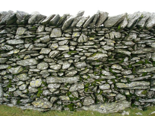
Dry stacked stone walls rely on strategically placed and compacted rubble to help bind the masonry elements together into a consolidated mass.  Good rubble will have a size distribution (big and small chunks) for space filling.  Proper use of rubble in dry stacked stone walls is an art.

Here’s to rubble.