Monday, February 27, 2012

The art of limits (and the limit of art)

Previously I described how the shape of the dimp masonry units describes a mathematical or geometric limit to design.  If triangular block are made on a simple two-piece mold, and blocks are to have the greatest possible interlock, then the shape I have uncovered is the limit within these parameters.  However, this shape as defined by these limits is not necessarily the best performing masonry unit.  Slight adjustments to these shapes make them more robust, easier to use and ultimately stronger.


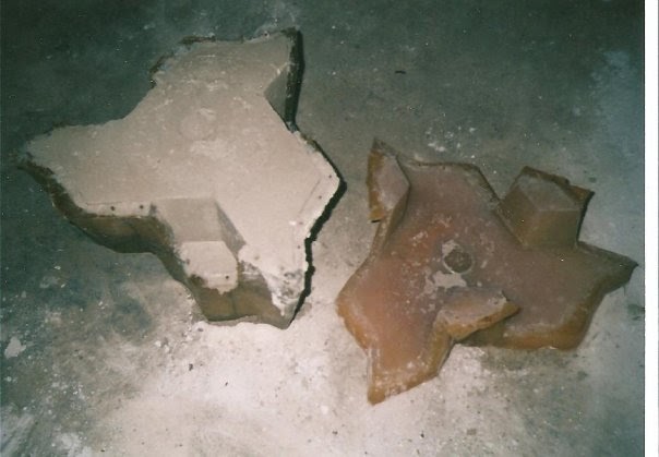
When describing these shapes, I refer to a “key” and a “keyway”; the key is a half-diamond shaped protuberance that sticks out from the block, the keyway is a half-diamond shaped recess that goes into the block.  At the limit of the dimp design, the key comes to a sharp triangular point.  This point will focus stress.  The bottom of the keyway recess also comes to a sharp triangular valley, which will also focus stress at this specific location.

Instead of having these sharp points at the key & keyway, they are “rounded off” so that forces are not focused at those locations.  Whatever amount of material is removed from the tip of the key must be added to the valley of the keyway, so that the key & keyway still line up and properly interlock between adjacent blocks.

How much the key gets “rounded off” is a tricky question.  It may be rounded by a simple radius, or it may be made to have a parabolic profile.  If the key is rounded with a simple radius, then a size of radius must be selected.  If too small of a radius is selected, then force will still be focused at a relatively small area.  If too large of a radius is selected, then the interlocking aspect of the key and keyway will be substantially reduced.  What is the optimum amount to round the tip of a key & keyway?  Should it be round or parabolic in shape?

These questions are truly interesting because this brings us to the intersection of art and science.  The equations required to describe this situation would be so utterly complex as to be practically unmanageable.   A number of competing mathematical approaches to solving this problem would provide different answers and different ways of viewing the problem. 

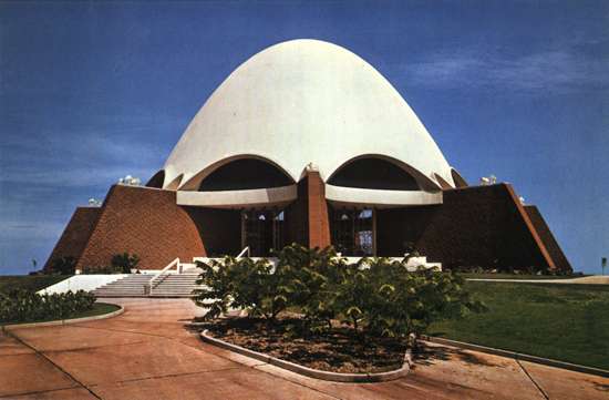
Instead, a person looks at the key and keyway and uses an intuitive sense to imagine: “removing this much would make it weak; removing that much would just not be enough; it seems like this particular arrangement feels about right.”  This sort of exercise draws on the experience, knowledge, skill and artistry of a masonry designer to provide an informed design decision.  Hard science and mathematics are left behind and art is picked up.  It is as though you feel it in your bones, like Brunelleschi and his dome.  This all occurs at the nexus of art and science.

A baseball pitcher may not have a full knowledge of acceleration, gravity, drag, rotational inertia, etc., but is able to use these principles to dramatic and skilled effect.  So it is when a person looks at a structure and imagines the weight, or force, or response of an arrangement to gravity or other stresses.  There is an intuitive knowledge which is developed with experience, study and practice.  These experiences inform the masonry designer and create a bridge from science to art.

Sunday, February 26, 2012

Concrete racing canoe competition?

The National Concrete Canoe Competition is a contest held in the US sponsored by the American Society of Civil Engineers (ASCE).  Different student teams compete against one another and plaques are presented for the winners in:

·         Best design paper

·         Best oral presentation

·         Best final product

·         Men's slalom/endurance race

·         Women's slalom/endurance race

·         Men's sprint race

·         Women's sprint race

·         Spirit of Competition


In addition, competition awards are distributed as follows:

·         1st place overall winner $5,000 scholarship & trophy

·         2nd place overall winner $2,500 scholarship & trophy

·         3rd place overall winner $1,500 scholarship & trophy

·         4th place overall winner commemorative plaque

·         5th place overall winner commemorative plaque


As stated on the ASCE’swebsiteThe ASCE National Concrete Canoe Competition (NCCC) provides students with a practical application of the engineering principles they learn in the classroom, along with important team and project management skills they will need in their careers. The event challenges the students' knowledge, creativity and stamina, while showcasing the versatility and durability of concrete as a building material.


Each year, the NCCC, which is held in mid-June, is hosted by an ASCE Student Organization. Teams qualify for the NCCC by placing first in one of the 18 conference competitions held throughout the United States during the spring. Teams placing second in a conference competition behind a university that finished in the top five at the previous year's national competition are also invited. To be eligible to compete the entrant school must be a recognized ASCE Student Chapter or ASCE International Student Group.


The winners of the ASCE National Concrete Canoe Competition are determined by compiling the team's total number of points from the academic and race portions of the competition. Academic scholarships totaling $9,000 are awarded to the winning teams' undergraduate civil engineering program.


Selection of the academic scholarship winner(s) is determined by the local ASCE Student Organization. The scholarship must be used toward satisfying tuition reimbursements only, and cannot be used to fund current or future Concrete Canoe competitions. ASCE must be notified in writing of the academic scholarship winner(s) prior to the distribution of funds to the recipients.”


Students learn much about concrete, team building, and –in general- have fun being involved in this project.  You might be surprised, concrete canoes are pretty fast!


Personally, I still prefer a Led Zeppelin to a Concrete Canoe.

Catenary reconsidered


Application of catenary structures must be carefully considered for use in different environments.  A few examples worth looking at include:

·        An environment without gravity.  If a structure is built in space, or acts as a satellite, or is built in conditions of very low gravity (like on an asteroid, or the moon, or even a buoyant ball) then the reasons for a catenary structure practically disappear.  Under these conditions a sphere or spherical dome is the optimal structure.


·         Very high external pressure.  If a structure is submerged to any depth, then an outside compressive force acts on the entire structure.  Under these conditions, again we find that a sphere is the strongest and most stable structure.  A catenary structure under great external pressure is weaker than a spherical structure.  (Do you ever crack an egg at the tip? No, you crack it on the weak side.)

·         Extreme loading from high velocity winds.  Such conditions are found in extreme storms, including hurricanes, typhoons, and tornadoes.  Under these conditions, the exposed surface area per unit volume is minimized by using a spherical form.  The profile is further minimized by using only a smaller segmental section of the spherical form, further reducing the profile of the structure.  A woven tensile geodesic web will help blocks resist suction forces in very high winds.

·         Earthquakes.  A catenary arch results from acceleration due to gravity.  In an earthquake, the ground can move in a sudden sideways fashion.  This results in acceleration in a sideways or lateral sense.   If a chain hangs from a rod, and the rod is tipped or inclined away from horizontal, then the catenary changes relative to the rod: the same way thrust force lines in a dome change relative to the horizontal ground movement during an earthquake. 

This situation is as if the arch was built on an inclined surface; the catenary still exists, but it is like a catenary on an inclined surface.  The direction of the inclined surface is relative to the motion of the ground.  The result of this sideways acceleration is that the catenary arch may eventually touch or exit the wall thickness; a hinge is created and the structure will buckle and collapse. 

Catastrophic failure of masonry arches during earthquakes can be prevented by using tensile elements woven into the arches as great circle arcs.  This geodesic tensile web will prevent the creation of hinges, catenary thrust force lines will not exit the wall thickness due to lateral acceleration.   Structural integrity is maintained if the hinges cannot open.   Tension is provided.

Tensile elements woven into a dome will help hold it together during an earthquake.

Tuesday, February 21, 2012

Catenary domes

The catenary form is key to understanding the design of masonry arches.  As discussed here, here, and here, “catena” is Latin for “chain.”  This word origin serves as a useful tool in analyzing the catenary arch.  This is because a chain hung slack is an exact analogy for a masonry catenary sprung arch, only it’s the opposite.  “Up” in a slack chain segment is “down” in sprung masonry arch; “tension” in a slack chain segment is “compression” in a sprung arch segment.  This fact provides insight by simply hanging a chain (or chains) and observing.


Some architects and designers use the term “funicular” when describing catenary arches.  Funicular comes from the Latin “funis” meaning rope or cable.  In terms of masonry, catenary is more accurate than funicular because the individual links of a chain are analogous to the individual blocks (voussoirs) of an arch; rather than the smooth continuity of a rope or cable.


A small chain will behave exactly as a large chain, in a proportional sense.  This reflects the scaleability of masonry arches, as discussed in earlier entries on Galileo’s wrong application of his Square Cube Law to masonry arches.  This means that application of Galileo’s Square Cube Law to chains is also wrong.  Chains are scaleable and do not need to be redesigned to be made larger.  Small models using small chains have direct application for larger models using larger chains.  Since the chain is a direct representation of the catenary arch, large masonry arch structures can be represented by small chain models.  Antoni Gaudi used this method to model the Sagrada Familia, as shown below.


Thrust force lines are the imaginary lines that indicate where the compressive force in a voussoir or block is located in the thickness of the arch.  In an arch, the thrust lines always describe a catenary curve.  If the thrust lines touch the inside (intrados) of the arch or leave the wall thickness, then a hinge is created and the arch or dome will buckle out and collapse.  If the thrust lines touch the outside (extrados) of the arch or exit the wall thickness, then a hinge is created and the arch or dome will buckle in and collapse.   In any masonry arch that stands, the catenary thrust lines are kept within the wall thickness; if thrust lines touch or leave the wall thickness then the arch collapses.


If thrust lines can be kept within thin walls, then wall thickness can be reduced.  There are different ways to keep the thrust lines within a thin masonry shell:

·         A smaller section of a dome can be used.  This smaller dome section creates an outward thrust or splay which must be contained by either buttressing the outside of the arch, or by having a tensile element inside the arch.  


·         If a half round arch is used, the thrust lines will be either close to, or touching, (or beyond) the intrados at a location in the arch known as the haunch.  By applying an external load to the extrados (outside) of the arch at the haunch, the thrust line is brought back toward the middle of the wall thickness.  By applying an external load (e.g., fill, rubble, etc.) to the outside of the haunch in a round arch, the arch can be kept relatively thin (this is somewhat counter-intuitive: that adding weight makes it stronger).   


·         Wall thickness can be reduced dramatically by simply making the dome as a catenary shell.  That is, instead of building spherical domes, they are made more “pointy” like the small end of an eggshell.  By making a catenary arch, the catenary thrust lines are kept within a very thin wall.


From a masonry perspective, the difficulty in assembling a catenary dome lies in the large number of different unit shapes required to make it.  The advantage of a spherical masonry system lies in the small number of triangular unit shapes needed to build a dome; they are all interchangeable (unlike a catenary dome).  Catenary arches can be made with different profiles, depending on how much slack the chain has.  Selection of the catenary arch which comes closest to a circular arch is advantageous.  By accounting for the slight differences in a true spherical dome and a catenary dome, assembly of a structure which comes very close to a true catenary can be achieved from triangular masonry units.  This is done by varying the thickness of mortar (or gasket material, as described here) and dihedral angles between voussoirs slightly as they are assembled.  This is most easily achieved by using a catenary-shaped form or support or bracing for the voussoirs to be assembled against.

In earlier entries (here and here) I discussed using an inflatable bladder as a form to support masonry units as they are assembled into a dome.  It is a simple modification to change a hemispherical bladder into a catenary-shaped bladder which can be used to support block as they are assembled into a catenary dome.  A dome with the thinnest walls, using the fewest number of unit shapes, in the strongest possible configuration is provided by using this method.

Friday, February 17, 2012

Tension cables in a masonry dome or sphere

The interlocking triangular block which I’ve developed and refer to as a dimp (dual inverse mirror plane) has a symmetry which allows a clear line-of-sight path along the center of each interlocking abutting edge of the block, as shown below.


This means that cable, or wire, or rope, or any appropriate tensile element can be incorporated into an assembled structure.  These cables can be placed on each of the three sides of a given masonry unit and woven together (I ask the reader to forgive my sloppy lines!).


A number of different types of regular polyhedra can be assembled from these triangular interlocking blocks.  These configurations can be used as templates for making spheres, or domes, or parts of domes.  The polyhedra which can be assembled from the hex and pent blocks include icosahedrons, dodecahedrons, icosidodecahedrons, truncated icosahedrons, and snub dodecahedron, among others.
Icosahedron

Dodecahedron

Icosidodecahedron

Truncated Icosahedron

Snub Dodecahedron

 In addition to the different polyhedral arrangements to choose from, different frequencies of these structures can be used to make larger or smaller domes or spheres.  Many different sizes of structures can be made from just a couple of unit shape triangular blocks.

As a given polyhedral dome is built, the first triangular blocks are laid on the starter course.  The starter course is a circular ring.  In between block anchors are cast in the concrete foundation, to which cables are attached.  These cables are placed in the abutting edge of the interlocking face and woven into the structure as it is assembled.  Shown below is a complete sphere being made, with a few of the cable loops pictured (I didn’t draw them all, it would be too sloppy).

Upon completion a sphere or dome has an interconnecting tensile web of great circle arc cables which hold the structure together.  Springs may be incorporated into the cable system to allow movement while also providing a restoring force, which will respond to any deformation by returning the structure to its original round shape.  The drawing below shows just some of the great circle arcs described by weaving cable elements into the abutting edges of blocks.

This tensile configuration system is applicable in cases where extreme loading conditions are expected.  This includes seismic activity, hurricanes, tornadoes, blast resistant structures, hardened structures, etc.

The combination of a mortarless gasket system (as described in my previous entry)  together with a woven tensile cable system creates an efficient, inexpensive, easy to assemble, high performance masonry construction method.

Thursday, February 16, 2012

Mortar, reconsidered

Mortar is used to glue masonry units together in a wall or structure.  As noted in an earlier entry, “it keeps blocks together and it keeps them apart.”  It combines masonry units into a consolidated structure.  It also keeps individual masonry units from touching one another.

Mortar typically has similar qualities to the masonry units it joins together: it is brittle and hard.  This quality of mortar does not allow it to act as a damper to blunt forces between blocks, like a fluid or ductile material would.  Mortar is effective at stopping cracks only insofar as it creates a boundary between blocks to blunt the energy focused at a crack tip.  Intimate bonding of mortar with block (what good joinery strives for) reduces the boundary effect of crack blunting. 


If a ductile material is used instead of mortar between masonry units, then a more toughened masonry structure can be built.  If the ductile material acts like a gasket and completely absorbs forces between blocks it will dampen and dissipate energy in a structure much more effectively than brittle mortar. 

In domes and arches, gravity acts to force the blocks together.  Masonry units can be assembled in a dome or arch without mortar.  The cementing or gluing effect of mortar is not needed to assemble a dome or arch; this is achieved by gravity acting on the masonry units, forcing them together.   The masonry units in a dome or sphere can also be held together by a tensile web of cable, or rope, or wire which is woven between blocks in a criss-crossing of great circle arcs into a net of tension, as I'll describe in my next entry.  If this tensile web is included, then the structure does not rely on gravity alone to hold it together.

Triangular block are particularly effective at distributing or dampening any applied force.  An individual block distributes any load or force to its 3 adjacent neighbors; these 3 distribute to their 6 adjacent neighbors; etc., rapidly and effectively dampening and reducing any applied load or force.  If this inherent dampening feature of triangular masonry units is coupled with a ductile, shock-absorbing, gasket-like material used between masonry units, then a very tough and robust structure results.

A ductile gasket material also make it easy for a domed or arched structure to relieve stress through conjugate shearing, as described here and here.

Currently I am investigating the possibility of using recycled rubber from tires as a material for gaskets to replace mortar in domes and arched structures. 


The two roles of mortar are to keep blocks together and to keep them apart.  If gravity is used to keep blocks together and gasket material is used to keep them apart, then high performance toughened masonry structures can be built without brittle mortar.

Wednesday, February 15, 2012

Nature's masons

Nature is the Grand Master of design.  Nature’s masons provide insight, inspiration, economy of design, appropriate use of materials and an array of different solutions for dwelling structures. Evolution’s solutions to appropriate homes for various living organisms showcase various masonry techniques.

Foraminifera (forams and radiolaria) are tiny single-celled organisms of ancient origin found in the oceans, exemplars of shell design.  Designs vary radically within foraminifera, from smooth spherical globules to spiky stellated stars; all forming calcareous hard shells.  It is amazing that a single-celled organism is capable of such exquisite design.


As foraminifera die and their shells sink and accumulate on the ocean floor over geologic time, this material forms sedimentary rock, including limestone, marble, and other sedimentary and metamorphic calcareous rocks.   Limestone is an ancient graveyard for countless of nature’s single-celled masons over the ages.   Foraminifera is life as a geological force.


One good example of nature's masons is Astrammina Triangularis, shown below.  This organism builds its shell out of small grains (masonry units) and assembles them in a triangular-based polyhedral arrangement.  

Coral is another example of nature’s masons.  Coral provides individual homes for countless individual polyps.  Coral builds on its own ruins of dead polyps, forming entire monolithic reefs of fabulous single-celled condominium units.  Coral is also a geological life form.

Sea urchins are a particularly interesting example of nature’s masonry.  These organisms have tough protective spines, made of calcite crystals embedded in an amorphous mixture of lime and protein, exactly like bricks in mortar.  The result is a hardened toughened structure, as I discussed in an earlier entry.  An assembly of small hard, crystalline individual masonry units creates a toughened, pre-fractured structure.  If this structure were one big crystal it would crack easily.  Nature has provided an elegant solution using masonry techniques.  Industry has taken note, and cement manufacturers are investigating and characterizing the structure of sea urchin spines for possible use in high performance concretes (HPC’s).


Turtles and Tortoises both employ a masonry design which creates an ideal portable dome home.   The carapace (top side) and plastron (underside) are two shell segments comprised of polygons.  Various species use patterns of polygons which create polyhedra which assemble into a dome.  Tortoises -living on dry land- have a more fully round, dome-like carapace.  Turtles -living in water- have a more streamlined carapace.  The shell of a tortoise or turtle is  typically made of 60 bones connected together in a masonry-like arrangement.  The shell actually contains nerve endings, and is a real living part of the turtle.  It is interesting to note that  the regular polyhedra known as Trapezoidal Hexecontahedra is also composed of 60 polygons, the "turtle of polyhedra".


Monday, February 6, 2012

The best masonry unit possible? Really?

I have written many entries on this blog describing a mass-produced triangular interlocking masonry system which I have developed.  I have attempted to describe some of the advantages of this system, and provided many examples both of this system being used, and how it could be used in various applications.  Today I will attempt to describe how this system represents a mathematical limit: that this system represents the actual limit of this design. 
 
First, we look at a basic question: why use triangular block?  To understand this, first we’ll take a look at domes.  Domes are sections of spheres.  Spheres can be described by subdivision into geometrical shapes.  In classical domes, this subdivision is done according to lines of latitude and longitude, so that the shapes are rectangular-ish or square-ish in their general aspect.  It becomes immediately obvious that the resulting blocks differ substantially in their size and shape, each from the other. 

The shapes around the ‘equator’ (or great circle arc) of a sphere are larger than those found at the poles.  The blocks from the “polar” area of a sphere cannot fit in the location of the “equatorial” areas, and vice-versa.  This means that these blocks must be custom made and precision fit to their individual specific locations in the dome or spherical section.  This creates a very large number of individual masonry shapes, and each must be made for its specific location in a structure.


In contrast, there are geometric bodies known as polyhedra, which are assembled from regular repeating unit shapes, each of which are interchangeable.  Each of these polyhedron approximates a sphere, or spherical section.  The regular geometric shapes which assemble into and constitute a polyhedron are triangles, squares, pentagons hexagons, and a few other polygons.  It is critical to note that any polygon with more than three sides can be made into triangles.   For example, a pentagon can be assembled from 5 triangles; a hexagon can be assembled from 6 triangles, etc.

This means that all regular polyhedra can be assembled from triangular shapes.  Each of these triangular shapes is interchangeable across the assembled dome or sphere.  This is in direct contrast with rectangular or square shapes which lines of latitude and longitude describe on a sphere or spherical section, such as a dome.  This means that the number of different shapes is reduced to a bare minimum, and that blocks are interchangeable in a structure.   This feature makes for a much easier and greatly simplified method of construction.

Second, we’ll take a look at creating an interlock between blocks.  The interlock provides a means of locating the block within the assembled structure: that is, the blocks are kept from sliding or otherwise moving outside the tangential surface of the shell,  dome, or sphere.  They are locked into radial position.  In my last entry I described the importance of this interlocking feature in keeping block located within the tangential curved surface of a dome.  If the block are free to slide out of the radial surface, a hinge is created, and the structure can buckle and collapse.  The interlocking feature thus makes assembled domes and arches much stronger, since the block are locked into their radial position in a sphere or dome. 

Third, these interlocking triangular block are able to be made on a two-piece mold without an undercut, or draft, or negative angle.  This is critical because it allows for the masonry shapes to be inexpensively and rapidly mass-produced.  If there is an undercut, or draft, or negative angle, then the unit shapes will not release from a mold: it is stuck and becomes hard to release.  A draft angle (or negative angle, or undercut) greatly complicates making the shape.  Sliding parts (to release a shape) and complex molds make such a shape uneconomical to produce.  It is instructive to note that concrete block are manufactured in matter of mere seconds.  To slow this process changes the economics of production, and the product so made is not economically viable.  It is critical to provide a simple two-piece mold without any undercuts, as shown below.


Fourth –and finally- the block must be able to be assembled without any draft, or undercut, or negative angle.   The masonry shapes must be able to slide into their assembled position.  If the structure (dome or sphere) must be “pulled apart” to allow the interlocking feature to engage, the structure cannot be built.  It is critical that there is not an undercut, or draft, or negative angle in terms of assembly.  For example, the blocks I’ve developed have a half-diamond key with an obtuse angle (at the tip of the key) of 120 degrees.  If the key were a half-square, with an angle of 90 degrees at the tip of the key, then there is a draft angle, or undercut, or negative angle which prevents the block from sliding together and being assembled.  In the drawing below, if the blocks had square- cornered keys, they could not be assembled; it would create an undercut.


The triangular interlocking masonry system which I’ve developed represents the mathematical limit of such a shape, and it simply cannot be improved upon.  If there were more of an interlock, the block would not release from a mold, and simply could not be made.  If there were an undercut in terms of assembly, then no structures could be built because the blocks simply couldn’t be assembled.

This was first pointed out to me by a team of mathematicians who attended my thesis defense, when I unveiled this design as part of my fulfillment for my degree in Masonry Science at Alfred University’s New York State College of Ceramics.  I am still only beginning to appreciate the significance of this mathematical proof.  Within the parameters I described in this entry, it is not possible to improve on this design; it reflects a mathematical and geometric limit of design. 

See about the art of limits here.  later this same month.