Friday, December 2, 2011

Masonry and wood


Corrado “Junior” Soprano:   “My father was a master stone mason.  He never cut fucking wood.”

-          From HBO’s “The Sopranos:  He is Risen”

Masons are known to sometimes be contemptuous of wood as a material, and of carpenters and carpentry in general.  Yet wood often plays a critical role in masonry construction.

Wood is tough.  In engineering terms, this means it is less prone to crack propagation.  Wood is also much less dense than stone or concrete.  It is also a good thermal insulator. 

Wood is sometimes used in a masonry type of construction, known as cordwood construction, stackwood construction, or stackwall construction.  Cordwood consists of logs that have been cut into lengths which are suitable for burning in a fireplace or woodstove, around 16 inches to around 24 inches in length (~40 cm to 60 cm).  This wood can be split or left in the round.  The length of the logs is the thickness of a wall to be built.  Nice thick walls: very strong and good insulators.


To build a cord wood wall, the logs are simply stacked as one would stack firewood.  A layer of mortar is placed between logs, much in the way mortar is placed in beds between rows of stone, block or brick.  The only real difference is that the mortar is typically half mortar and half sawdust.  This makes the mortar a better insulator, and much less expensive.  Sawdust in large quantities can usually be obtained from your local saw mill, either for free or very inexpensively.  It is simply added to dry mortar, dry mixed, and then further mixed after water is added.  For greater strength, holes can be drilled through the logs and they can be spiked together, as is being done in the picture below.


I am currently building a combination log cabin/cord wood building.  I’ll be using it to contain a sauna, with a bedroom upstairs.  The upstairs walls are all cord wood construction.  Some people like to include glass bottles in their walls to allow light to pass through.  I used a bunch of handblown glass spheres in my walls.


I must warn the reader that if he or she ever decides to do this, one must be very careful with the chainsaw.  I almost cut my left foot off last week.  I’m sitting here typing now with a big cast on my foot; I’m very lucky I didn’t lose my foot!  I just got back from a week in the hospital.  I had to be flown out on a helicopter.  Please be cautious.  I was working alone.  I knew better, but was racing the onset of winter.  If I were a master stone mason, I would never cut fucking wood, and I would never cut my fucking left foot.  Foolish me.

I apologize for cursing on this entry to those who may be offended, but it really hurt.

Here is a picture of the finished sauna building:
 

Friday, September 30, 2011

Preparing a Forced-air Wood Kiln

Here's a short video showing my wood kiln, which is almost ready to fire for the first time.  This is the first forced-air wood kiln I've ever seen.  Forced-air means that a fan is used to create the draft.  Normally a wood fired kiln does not use a fan, but instead relies on a tall chimney to create a suction or draft through the convection process of heat rising through the tall chimney.

The fire box is set slightly off-center (to the right) which was done to creat a swirling vortex.  This vortex extends the flame path through the firing space, providing more complete combustion and more even temperatures.

Initially this kiln was a gas-fired forced air kiln, built as a prototype under a grant I received from the New York State Energy Research & Development Authority (NYSERDA).  Originally it had 3 burners, each capable of producing 750,000 Btu per hour.  I built another conventional rectangular kiln of the same size, same wall thickness, same burners, etc., for the purpose of comparison.  My kiln proved to be 37% more efficient than the rectangular kiln, which is really quite an improvement.  This kiln is a downdraft, meaning that the hot flue gas vents at the bottom center of the kiln.

I adapted the original gas-fired design to a wood-fired configuration simply to see if it would work.   This is one big experiment: if it works well, it should fire faster than a conventional wood kiln.  A conventional wood firing usually takes around 3 days.  I'm hoping to cut that time substantially.  We'll see!

Tuesday, September 27, 2011

Ceramic Spheres: a Work in Progress


I am currently preparing to make a series of fired ceramic masonry spheres, around 3 feet in diameter.   These spheres will utilize the interlocking triangular design which I’ve developed over the years.  The image below is from an electronic file created by my business partner, Mike Wong.  This same file will be used to produce the master shape from which molds are made.

I plan to produce the ceramic shapes from plaster molds.  These molds will be made from a CNC (computer numerically controlled) machined master shape.  I expect the master shape to be made from wood.  The key to doing this efficiently is to cast the ceramic parts from a simple two-piece plaster mold.  More than two parts for a mold makes production difficult, time consuming and expensive.  Below are images of blocks made from a two-piece mold for a kiln I made, as discussed here.


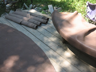
The geometry I’ll be using for this sphere is that of an icosahedron.  There are twenty pieces in an icosahedron, each is an equilateral triangle.  The shapes will be curved, like those on the right, below:

I’ll probably use a series of thin metal bands on the outside of the sphere to help hold the sphere together and make them easy to transport.  I expect these to look pretty cool, like a modular spherical UFO of a barbeque!

These complete spheres will have a rectangular door on the side.  I plan for this door to be a simple hinged arrangement, with a hinge at the bottom. 

These spheres can be used for pizza ovens, barbeques, smokers, or simply as ovens.  I’m curious if anyone reading this can think of another use for this sized sphere?

I plan to configure these so that they can run on propane, natural gas, wood or charcoal.  I plan to have the burner port on the bottom and the vent/chimney on the top.  I also plan for the flame to be slightly tangential (offset from center) so that a swirling vortex is developed within the firing space.  This extends the flame path, creates more even temperatures, and increases efficiency.

The thermal mass effect of the ceramics will help provide radiant heat and even temperatures throughout the firing space.

I will post additional entries on this forum as the project moves along.  Right now I have around 25 tons of clay sitting in my driveway, which I’ll be using to make these spheres (right now I'm racing against winter!).  If all goes well, I should be able to make between 500-1,000 of these spheres.  This should be fun!

[Here is an update on this project]

Sunday, September 11, 2011

Energy Budget for Desalination

I’ve done a few postings (here, here, and here) on an idea for desalination (creating fresh water from saltwater) using a concrete sphere which is submerged to a great depth (~2,225 feet) to use the pressure at that depth to force saltwater through a reverse osmosis membrane.  The sphere -filled with fresh water- is then taken to the surface and the fresh water is harvested.


Today I’m looking at the “energy budget” necessary for this approach, and I compare it with existing reverse osmosis technology.  Due to global warming and rising sea levels, the availability of fresh water along coastal areas is a diminishing resource.  Humans have a growing need for potable water, which may be satisfied in part by desalination (desal) technology.  Because current desal technology requires large amounts of energy, any energy savings could be hugely beneficial.  Currently this energy comes primarily from burning fossil fuels to generate electricity: it is not a sustainable approach and will further contribute to anthropogenic global warming (AGW).

I begin by looking at the energy requirements for current desal technology.  In this source, the author reports that desal plants use around 5kWh of energy per cubic meter of fresh water produced.  Commenter’s feedback on this article report that greater efficiency can be expected: from between 3.4 – 4.5 kWh/m3; to possibly as low as 2.2 kWh/m3.

Main author says: “The most efficient (reverse osmosis based) desalination plants consume about 5 kWh of energy per cubic meter of fresh water produced. The fundamental thermodynamic limit for desalinating seawater is 0.86 kWh m−3.”

Commenter says: “One minor point to note is the energy numbers – your source of 5 kWh/m3 is from the IAEA in 1992. Today, this would be considered a very conservative number. Using energy recovery technology such as the PX (Pressure Exchanger) from ERI (www.energyrecovery.com), the SWRO process can consume under 2.2 kWh/m3. A 2008 study by the National Academy of Sciences (www.nap.edu/catalog.php?record_id=12184) puts the number at between 3.4 – 4.5 kWh/m3.”

If we look at my approach of sinking an empty concrete sphere, the main work needed for this is sinking the buoyant sphere to great depth.  I use a simplified approach, looking at 1 cubic meter of air, sunk to 2,225 feet below sea level, where a pressure of just over 1,000 psi is obtained; enough to force sea water through a semi-permeable membrane, removing the salt component.

On doing some more research, I've come to realize that apparently there are reverse osmosis (RO) filters that will perform this work at a depth of only 850 ft. (260 m) as developed by DXV Water Technologies.  This approach is described here (see pp. 2-3).  While this method uses the static head pressure at depth to help power the RO filtration, it still relies on a pump to bring the water to the surface.  This article states that "Many readers have grown numb to reports of new desalting techniques claiming energy reductions of 50 percent or more."  Furthermore, there is a history of people claiming the ability of "free" desal technologies which amount to perpetual motion machines (an impossibility: violating the 2nd Law of thermodynamics).  Low flow rates through an RO membrane achieve higher efficiency.  As the flow rate increases, efficiency drops exponentially.  Thus a large number of large volume spheres, operating at a low flow rate would achieve higher efficiency while still achieving higher volume. 
I simplified my analysis by considering the density of water as 1.0 g/cm3 (seawater has a density of around 1.025 g/cm3).  I also consider the act of bringing the water to the surface as negligible.  This is because the water to be harvested is considered as neutrally buoyant.  Because it is neutrally buoyant, there is no gravitational acceleration, and no work is required to move the object (this is a simplification).  In fact, extra work will be required to overcome turbulence and drag (viscous effects): 

The total amount of work required to lift a nearly-neutrally buoyant object through a viscous medium has two terms, the gravitational term W = \Delta\rho V g \Delta h and a drag force term, the force required to overcome viscous effects. This has to be written like W =\int f dl , because the viscous drag will depend on the path taken- straight up, zig-zag, whatever. The drag force f can be written simply as \mathbf{F}_d= {1 \over 2} \rho \mathbf{v}^2 C_d A.   One simplification is to tow the body at constant speed, then you are left with a simple multiplication rather than an integration.

I am ignoring these viscous effects because it varies greatly depending on the size of the sphere.  I do not expect this effect to “break the budget” for energy used in this process.

If we crunch the numbers, here’s what I got:

Work = Force x Distance = Buoyant force x distance submerged

Distance =2,225 ft. = 678.18 meters

Work = Mgh = 1,000,000g x 9.8 m/s2 x 678.18 m = 6646164000g m2/s2 =6646164 Joules

Joule = kg x m2/s2   kWh = 3,600,000 J

(6646164J) x (1kWh/3,600,000J) = 1.846156 kWh (energy required to submerge 1mof air 2,225 ft.)

So there’s my number: 1.846 kWh to get 1 m3 of water at 2,225 ft. below sea level.  At  850 ft. below sea level, this works out to just over 0.7 kWh/m3, which is right around the thermodynamic limit.  You couldn't do much better.  How does this compare with existing technology?   The deeper we go, the faster water is produced; but much less efficiently.

If we compare 2,225 ft. below sea level with:

·         5 kWh/m3 it requires 36.92% of that energy.

·         4.5 kWh/m3 it requires 41.02% of that energy.

·         3.4 kWh/m3 it requires 54.29% of that energy.

·         2.2 kWh/m3 it requires 83.90% of that energy.

A few important notes on these preliminary numbers:  If more efficient reverse osmosis membrane filters are used, then the sphere does not need to be sunk to such a great depth, and energy savings translate directly to the sunken sphere approach.  This keeps my approach very competitive.

If it is possible to use weights (e.g., landfill, etc.) to sink the sphere, then NO ENERGY is required to obtain fresh water!  This may not be a realistic or sustainable approach.  It would involve dropping massive amounts of material on the ocean floor to sink the hollow spheres.  Still, it is a possibility.

I have neglected the weight of the concrete sphere itself.  This is because the ratio of the weight of the sphere to the volume of water varies extremely, depending on the size of the sphere.  This weight will reduce the amount of work done to sink a hollow sphere, but will add to the work needed to bring the freshwater to the surface.
I have also disregarded the two stages (minimal) necessary for producing potable water.  As described above, this process will merely produce brackish water.  There are methods using this same principle to achieve potable water; I'm just not sharing everything on this forum.  The energy analysis outlined still works for creating potable water.
This short mathematical exercise indicates that potentially significant energy savings can be obtained by using the approach I’ve described for desal.  If anyone out there wants to double-check my math and let me know if I’ve made any critical mistakes, it would be greatly appreciated!

Wednesday, August 17, 2011

Insulating Concrete Forms: Greatly Improved

Insulating Concrete Forms (ICF’s) are a relatively new method of construction.  ICF’s provide many features which are advantageous to the owner.  ICF is gaining acceptance and use as a method of construction both nationally –here in the US- and internationally.
ICF’s are typically like large hollow rectangular blocks made of Styrofoam type material.  These blocks are stacked and the hollow core is then filled with ready mix concrete (delivered in a concrete truck).  Steel rebar is typically placed in the wall cavity for tensile strength.

The resulting structures are very strong, well insulated, relatively inexpensive and easy to assemble.

Here are some of the benefits of ICF construction, as described by the ICF Builders Network:

Energy related:

High performance R-values

No air infiltration

Permanent performance no downgrading over time

Shifts thermal loading from peak periods

Lower cost to heat and cool

Health related:

No air infiltration means no dust or allergens

No cavity walls for mold, mildew, bugs or rodents

Non-toxic materials

No off-gassing of materials

Structural related:

High wind resistant

Fire rated assembly

Strength is permanent

Will not rot or decay

Resistant to termites (the concrete)

Impact resistant

No maintenance requirements

Comfort related:

High sound attenuating

Enhances steady temperatures

Peace of mind during inclement weather events

Low maintenance structure

May attribute to lower insurance costs

Constructability related:

Design versatility

Energy efficient

Structurally capable

Fire rated

Sound deadening

Quick (depending on installer)

Conducive to Exterior Insulation Finish Systems (EIFS)

Permanence

Fully code accepted cast-in-place concrete walls

Time tested and proven

ICF construction is indeed advantageous for all those reasons listed above.  However this type of construction can be made even better and this is what I’ll be talking about today.

Problems with ICF

First, thermal mass benefits associated with ICF construction are not truly maximized.  This is because heat is stored in the concrete, where it is subsequently released to the interior space of the building.  In order for this thermal mass effect to be efficient, the heat should be readily transferrable between the concrete of the wall and the interior of the building.  ICF construction insulates between the interior space and the concrete wall.  That is, there is foam insulation on the inside wall; this insulation prevents heat from travelling between the interior space to the concrete wall, and also prevents heat from being released from the wall to the interior space.

As I discussed earlier on this blog, thermal mass benefits are maximized if the exterior surface of a concrete or masonry wall is insulated.  When the inside surface of a wall is insulated, the thermal mass benefits are reduced.  Insulate the outside for maximum efficiency: insulating the inner surface of a wall reduces thermal mass benefits.  ICF methods insulate the inner surface of the wall.

Another shortcoming of ICF technology is its inability to provide an effective roofing system.  Currently ICF technology is only used to make vertical walls.  It is generally not used for roofing.  If ICF technology could be used for roofing systems, the benefits of this technology would, quite simply, extend to the roof. 

Currently, a close cousin to ICF’s can be used for roofing.  This technology is known as Structural Insulated Panels, or SIP’s.  One of the disadvantages of SIP’s is that they are not poured in place, like ICF’s, but are pre-cast, and must be placed with a crane.  A truly integrated system which would bring the ICF approach to roofing would provide a simplified construction, using the same technique for the entire building envelope, including the roof.  With such an approach, all of the benefits associated with ICF construction –as listed toward the beginning of this post- would extend to the entire building structure, including the roof.  SIP's commonly do not incorporate concrete, and are not as strong as the rest of an ICF building: this is a weak link.


A Whole New Approach

What is described below is frankly a much better approach to ICF construction than is currently practiced by industry today.  This method greatly increases thermal efficiency and maximizes thermal mass benefits of a concrete wall by not insulating the interior of the concrete wall.  It also extends the ICF construction method to the roof, and brings all the benefits of ICF construction to the roof.

First, an inflatable bladder is set up and inflated.  This bladder provides the formwork, scaffolding and support for the ICF triangular blocks.  This bladder is essentially the size and shape of the interior space of the finished building.  The concrete is poured from the top, and allowed to flow directly against the inflated bladder, which creates the interior surface of the form.  This means that no insulation is wasted to insulate the inner surface of the building.  It also greatly reduces the amount of foam insulation required for ICF construction, increasing thermal mass benefits and efficiency.

Second, ICF forms are assembled around the inflated bladder.   These triangular forms utilize the interlocking design, and are further strengthened and reinforced by the tensile elements (e.g.: steel cable, rebar, etc.) which are woven into the walls and roof as they are assembled.  This approach allows for extensive design flexibility, and can include vertical walls, square corners, cylinders, arches, domes and any combination of these elements.  These shapes will be hollow, and made from foam.  They assemble around the inflated bladder.

The ICF forms shown in this schematic patent illustration are able to be made on a simple two-piece mold without any undercut.  This greatly simplifies their manufacture, and makes them inexpensive to produce, as described in one of my stupid poems.

To make a roof, the bladder is inflated, the blocks are assembled, and concrete is then poured from the top and allowed to flow down to form a consolidated, massive wall.  There are holes in the sides of the triangular foam blocks which allow the concrete to flow between blocks; from the top of the pour to the bottom of the foundation.

If the building’s height is too great to withstand the weight of wet concrete, and a blow-out would result, then the building is simply assembled and poured in smaller vertical sections, so that the head pressure of wet concrete is reduced, preventing a blowout.  Once a section is poured and cured, then additional foam block are added for the next section to be poured.

Once the building has been poured and the concrete has been allowed to properly cure, the bladder is simply deflated and removed, and is ready for another job.  The interior wall of the structure is now exposed concrete, providing increased thermal mass benefits and efficiency.

These bladders are commercially available, and create a very effective scaffolding and formwork: as I described earlier on this blog, here and here.

By using this construction method, what is created is much stronger, faster to assemble, less expensive and able to withstand hurricanes, tornadoes, earthquakes and other severe structural loading events. 

Currently my company is seeking a partner to bring this technology to market.  Too many ICF manufacturers seem “in love” with their own technology, and are unwilling to see beyond current practice in industry.  This is a huge opportunity for the right organization.  We may just “bootstrap” this technology and launch it ourselves.  It is an exciting time!
I covered a lot with all this.  Questions?  Comments?  Drop me a line.

Friday, August 12, 2011

A Very Intriguing Theory: Bricks and DNA?


Yesterday I began a description of arches meeting at right angles, and how this unique arrangement might possibly be found in DNA molecules, in structures known as centromeres and telomeres.  I realized today that I’ve already written about this odd masonry detour back in April, 2010.  So today I borrow from this earlier entry and expand a little, since it is a pretty interesting subject .

The system I described yesterday is some interesting geometry, I think it's fundamental and basic, and may well exist in nature. In particular, I propose that it may exist in features of DNA.

Most of you probably know that DNA is a double helix. Think of the double helix of DNA as forming a big "X". The ends of the 'x' are telomeres, the center of the 'x' is the centromere.

Centromeres are an originating site of DNA replication (copying begins here). Telomeres are a terminating site of DNA replication. It is proposed that the structures of telomeres and centromeres approximate a structure wherein a combination of four right circular cylinder sections (whose 2 axes of rotation are at right angles to each other) of radius = 1; and also of a section of a hemisphere of radius = 1.5. Here the double helix of DNA is viewed as a right circular cylinder of radius = 1.5. Cylinder sections combine (superimpose) with a spherical section through a four-fold axis of rotation. The geometry of this arrangement may create two optimal energy states simultaneously. This arrangement may be seen as a natural attempt to “square the circle.”


Background

A telomere is a region of repetitive DNA at the end of chromosomes, which protects the end of the chromosome from destruction. Derived from the Greek telos (end) and meres (part).

During cell division, the enzymes that duplicate the chromosome and its DNA can't continue their duplication all the way to the end of the chromosome. If cells divided without telomeres, they would lose the end of their chromosomes, and the necessary information it contains. (In 1972, James Watson named this phenomenon the "end replication problem.") The telomere is a disposable buffer, which is consumed during cell division and is replenished by an enzyme, the telomerase reverse transcriptase.

This mechanism usually limits cells to a fixed number of divisions, and animal studies suggest that this is responsible for aging on the cellular level and affects lifespan. Telomeres protect a cell's chromosomes from fusing with each other or rearranging. These chromosome abnormalities can lead to cancer, so cells are normally destroyed when telomeres are consumed. Most cancer is the result of cells bypassing this destruction. Biologists speculate that this mechanism is a tradeoff between aging and cancer.

I propose that the following geometry may be present in a telomere:

The centromere is a region, often found in the middle of the chromosome, involved in cell division and the control of gene expression. I propose that this geometry may be present in a centromere:

Why bother with this? Centromeres are largely responsible for cell reproduction, when centromeres malfunction genetic disease results; telomeres are largely responsible for aging. Any insight into the functionality of these structures is important to science and medicine.

Here's an interesting article on how geometry can have a direct effect on gene expression. I owe this reference to Alan Michelson, who brought it to my attention, as if to say: "maybe you're not so crazy Pete." Thanks Alan. Here's the article.

Yesterday I began trying to describe the possibility that a particular helicity of cylindrical sections meeting at right angles -into a larger sphere- may be found in structural sections of DNA known as telomeres and centromeres. To summarize this theory with images, a telomere may have a "turn-in" type structure:

A centromere may have a "turn-out" type structure, shown as:


The important aspect of this arrangement is not the individual triangular units, but the helicity and the larger spherical section of the larger assembled structure. It seems that nature is attempting to square the circle with this arrangement.

Below is a view of a telomere, looking at the end of a section of DNA, essentially looking down the "cylinder" of the double helix of DNA. The helicity of DNA changes as a chromosome replicates itself, and it seems that this helicity is what is described in those right angle intersections shown above. Here is a view of a telomere, note the quadrature, or squaring of the structure:


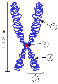
Below is a view of a centromere, with a view of the entire chromosome. This illustration shows how four cylinder sections intersect at a right angle. Centromere is shown as feature 2.


I propose that DNA, through telomere and centromere sites, may utilize this geometry. The ‘turn in’ corresponds to a telomere, and the ‘turn out’ to a centromere. The cylinders may be taken as base sections, or spindle poles. These arrangements may provide an intermediate energy state; somewhat analogous to a catalysis reaction.

A catalyst works by providing an alternative reaction pathway to the reaction product. The rate of the reaction is increased as this alternative route has a lower activation energy than the reaction route not mediated by the catalyst. The geometry described here is analogous to providing an alternative route with lower activation energy.

The centromere and telomere structure are similar to fullerene molecules in a few striking ways. The presence of hexagons and pentagons within the base sections is a feature the telomere shares with fullerenes. Cylinder and sphere sections are found in both centromes & telomeres and fullerenes. It is proposed that centromeres & telomeres create a lowering of thermodynamic or activation energy ‘threshold’: the same is true of fullerenes as evidenced by their existence in nature.

Currently the vast majority of genetic research is empirical, not theoretical. That is, functions of genomes are determined by seeing what effect manipulating (e.g. removing, etc.) a particular genome has on the design/function of the organism it describes. This approach disregards the geometry of DNA, and does not allow certain theoretical insights, which may otherwise be gained. Consideration of geometry may indicate thermodynamic ‘net gains’ that might point to functionality of chemical states.


Close examination of DNA geometry seems to have slowed immensely since Watson and Crick discovered the double helix. DNA is more than a ‘blueprint’; it is the blueprint, architect, engineer, construction worker and building inspector. It is more than these analogs; it is the actual thing itself. This appears to merit a close inspection of its structure and geometry in order to more fully understand it. If this theoretical (geometrical) approach is coupled with the knowledge gained from the empirical approach (i.e.- mapping of the human genome) then a much deeper level of understanding may be obtained.

A cell creates itself and closes itself off. It has genesis and distinction (becoming distinct, having a boundary within which it exists). This geometric model works for the combination of origin (sphere) and growth (cylinders). This is somewhat analogous to the thermodynamic conditions necessary for nucleation and growth in crystal formation. Duplication results in 2 spheres as distinct cells. The separation and distinction of 2 from 1 embodies or relates directly to the activation energy threshold.

We've had a look at one possible role of geometry, to try and show that geometry can play an important role in how things work.

Today there was an interesting article posted by Physorg.com on carbon tubes and water.  This remains a fascinating topic which merits further investigation.
I am unaware of anyone who may have stumbled across, or is investigating, or is even aware of the geometrical structure which I propose exists in the centromere and telomere structures of DNA.  I think this is worth looking at.


Thursday, August 11, 2011

Arches at Ninety Degrees

Back in 2000, I had an insight into vaulted arches.  I had been developing triangular interlocking block as a masonry system, and had devised of a method for making cylinders from these triangular blocks.

A cylindrical section can be turned horizontally to create a vaulted arch, like a roman or circular or barrel vault.  

People are largely used to living in a square-cornered building or house.  There is something fundamental to the human psyche that looks to straight walls and square corners within a living space as a standard which sets people at ease.  Domes and round buildings make up a tiny fraction of habitable structures: almost all buildings have straight walls and square corners.  As you read this now, look around you at the building you are in.  I'd be willing to bet that it has straight walls and square corners.  If not, you are in a very tiny minority, living in an "alternative" structure.

It is a challenge to make a vaulted arch roof system sit atop a square cornered building.  In my own masonry approach, which uses triangular block to assemble a cylinder or arch, the triangles can be assembled to provide a helical or spiral edge.  A helix or spiral has translation and rotation, and the 'helicity' or angle of 'spiralness' can be varied.  Think of stretching a slinky: the spiral angle of translation and rotation can be varied, from shallow to steep angles of helicity.

If the translation versus rotation of a given cylindrical section is equal to the radius of the cylinder versus 90 degrees, then this helicicty can be placed atop a right-angled base.  It is thus possible to place vaulted arches atop a right-angled structure.  The right angle can be a "turn-in" as shown below, where the angle between walls is simply 90 degrees, as shown below. (taken from one of my patents)


Below is shown a structure where the vaulted arches are shown as a "turn out" where the walls meet at 270 degrees.  In the case of both a "turn-in" and a "turn-out" a gap is created between the helical edges of the abutting arches where they meet at a corner.  This gap is satisfied by a larger spherical section.  Specifically, if the arches are taken as having a raius of 1.0, then the larger spherical section that fills the gap has a radius of 1.5  (If you'd like to see these images better, just click on them to see a larger view).
This sort of arrangement provides extensive design flexibility.  One, two, three or four vaulted arches can meet at right angles to each other, merging seamlessly into a larger dome or spherical section.

This arrangement creates some very interesting possibilities far outside the realm of masonry.  Could this arrangement have something to do with the structure of DNA and the "magic" of reproduction?  We'll take a look at this next time, including a discussion of centromeres and telomeres.

Tuesday, August 9, 2011

brick & mortar


Brick & mortar” has come to mean a real, built thing; as opposed to a virtual or digital thing.

Masonry is real, it is meant to last over time.  Masonry construction reflects a confidence in the future.  It is not temporary.
Markets rise and fall; sometimes dramatically.  This is temporary.

Planning for masonry construction during such times displays confidence in a real outcome with an actual brick & mortar result.  In today’s economy, long term thinking and planning are often at odds with quarterly results.

Those with foresight have chosen masonry construction throughout history.  We are left with testament to their optimism with everything from the Pantheon to the Brooklyn Bridge; the Hagia Sophia and Notre Dame Cathedral, all brick & mortar. 

Monday, July 18, 2011

Air supports masonry?

Air is one of the lightest materials, whereas masonry is one of the densest.   It seems improbable that air can be effectively used to support and enforce masonry.  But that’s what I’m looking at today.
A number of innovative approaches to using air as a structural support member have been developed and introduced over the past decade or so.  Some of the most intriguing of these applications involve bridges.

For example, textile composites are used as a framework for inflatable structures.  As discussed here, these inflatable elements are used to provide arches in a concrete bridge.  The arches are made of a membrane inflated with air which serves as a support form or scaffolding while the concrete bridge is constructed.   This approach means that no rebar is necessary; no wooden formwork or other difficult, expensive scaffolding material is required.  The inflated tubes shown above are treated with resin and solidified, then filled with concrete.  These cast curved tubes (or toroidal sections) of concrete are especially ductile, yet very strong.
A number of approaches have been used to provide high-strength inflatable bridges, such as those shown below:


There is an elegant simplicity to using an inflatable element as scaffolding for massive masonry structures.    An inflated surface, or bubble, represents a least energy surface.  There is a balance between the force of the inflated –or pressurized- air, and the tensile strength of the membrane, or “bubble”.  This balance results in a least energy surface.

The simplest of these surfaces is a simple round sphere.  These surfaces can also be tubes, cylinders, and combinations of these elements.  As we look at more complex shapes, we quickly enter the mathematician’s and geometer’s realm of topography.  There are saddle shapes, ‘monkey saddles,” parabolic and hyperbolic curves, even catenary configurations.  Each of these represents a least energy surface.


I am currently experimenting with an inflatable bladder to be used as scaffolding for constructing a masonry sphere.  I am assembling a rubber sphere, which is configured like a ‘beach ball.’   This will be used to assemble masonry spheres below ground, for water storage tanks, septic tanks, and other similar applications; around 8 feet in diameter.  For this use, the sphere will be inflated to a relatively low pressure (~20 psi) and will support block as they are laid.  Once the sphere is complete, the inflatable bladder is deflated and removed.  It is incredible (to me, at least) how much weight a relatively low air pressure can support.  25 psi can hold up tons of block!
Although my test sphere will be relatively small, it will be scale-able.  If the proportions remain intact, then a much larger sphere can be made using the same approach.  As discussed earlier, Galileo tried to impose his square cube law on masonry structures, and he was WRONG, the ancient masons had it right:  scale-ability is one of the defining features of masonry design.  The same system used to build an 8 foot diameter sphere can also be used to build an 80 foot (or 800 foot!) diameter sphere.


Other dome manufacturers use inflatable bladders for their systems; notably Monolithic Domes, as I discussed earlier, here.  Their use is for spraying shotcrete though, not for support and assembly of masonry construction.

As I use my inflatable bladder for masonry scaffolding I’ll post updates and pictures on this blog.  In the past I’ve used wooden scaffolding, I expect this to be much, much easier, faster, safer and cheaper.