Monday, January 30, 2012

Interlocking Triangular Block and Shell Theory

In my last entry I introduced shell theory as pertaining to masonry domes.  The essential aspects of this theory include a thin-walled, doubly curved structure.  “Thin walled” is not exceeding one tenth of the radius of the arch or dome.

Much work has been done on Finite Element Analysis of domes and arches.  A couple good examples of research which include literature surveys of this topic include “Limit state analysis of hemispherical domes with finite friction” (D. D'Ayala and C. Casapulla) and “Structural Assessment of Guastavino Domes” (H.S. Atamturkur).  These two academic papers provide a rather complete analysis of FEA methods used by the authors and include a decent look at research by others in the field.

As I stated before, FEA is –in my view- an imperfect method for analyzing masonry domes.  I find Thrust Line Analysis to be a more insightful approach to understanding the forces, stresses, strains, and failure mechanisms within masonry domes.  The visual representation of thrust lines within shell thickness gives a direct representation of stress within the wall thickness, whereas FEA typically use different shades of color for different stress levels over the entire dome.  Excellent work on thrust line analysis in masonry domes has been done by Philippe Block, Thierry Ciblac and John Ochsendorf at Massachusetts Institute of Technology, as described in their paper “Real-time limit analysis of vaulted masonrybuildings.”


A thrust line is a visual representation of the force present in a given block or voussoir within an arch.  If the thrust line is kept within the wall thickness, then the structure is stable and will remain intact (as shown below).  If the thrust line leaves the wall thickness or even touches the wall boundary, then a hinge is created, the structure can buckle and fail or collapse (as shown above).


A masonry shell is strongest if the thrust line is kept at the center of the wall thickness.   The masonry unit, or voussoir, or block is strongest and best able to bear its load if the thrust line is in the middle of the block. 

If an individual block moves or slides out of the shell’s curved plane, then the thrust line will be closer to the inside of the block.  This can create a hinge if the thrust line touches the inner surface of the block, possibly resulting in failure and collapse of the dome or arch.  It is critical to keep individual masonry units in the curved surface of the shell.


The symmetry of the dual inverse mirror plane (dimp) blocks as discussed in this blog creates an interlocking feature which prevents blocks from moving outside of the curved shell surface.  Blocks are effectively locked into the tangential plane of an assembled spherical section.  


This symmetry also creates a “line-of-sight” exactly in the middle of the block, halfway between the inside and outside of a dome.  This line of sight allows for a wire, or cable, or other tensile element to be woven between adjacent blocks.  This geodesic tensile web within the center of a masonry shell (feature 660 below) serves the purpose of keeping blocks located within the tangential plane of the dome, arch, etc.  


Shell theory in a masonry dome analyzes deflection of the shell surface under various loading conditions.   Deflection or movement of the shell weakens the shell because the thrust lines can then reach the inner and outer surface of the masonry wall, resulting in a hinge being created; failure and collapse.


Since the “dimp” blocks are configured with key and keyway symmetry; together with the line-of-sight at the center of the abutting edge of each block which allows a woven tensile element, all blocks are effectively prevented from deflecting or moving outside of the tangential curved surface of the masonry shell.  If the blocks cannot move out of the shell, they are much less prone to failure or collapse. 


Friday, January 27, 2012

Shell Theory and Masonry Domes

Shell Theory is a field of physics, mathematics, architecture, topography and engineering which provides insight into masonry dome structures.  Today I’ll be looking at Shell Theory in the context of many topics which I’ve already written about on this blog, and tying several things together toward some valuable insight into masonry dome and arch structures.
Shell Theory has its roots in the Euler–Bernoulli Beam Equation (also known as the “engineer’s beam theory”, “classical beam theory” or just “beam theory”) which was developed around 1750.  This theory describes a means of calculating the deflection and load-bearing capacity of a beam.  This theory was not fully utilized until the late nineteenth century, with the construction of both the Eiffel Tower and the Ferris Wheel.  This theory played a major role in the engineering developments of the Industrial Revolution.

The Euler-Bernoulli equation describes the relationship between applied load and deformation, where E is the elastic modulus; I is the second moment of area; w is the deflection of the beam at some point, x; and q is the distributed load.  Don’t be scared by this equation!  It says if you push a beam this hard, in that place, it will bend this much, that’s all.

Plate Theory is an expansion of beam theory to thin-walled structures, or “plates.”  The plate is assumed to be thin enough that it can be treated as a two-dimensional element, rather than as a thick beam, as in beam theory.  Plates are assumed to be flat, or planar.

If the plates (in plate theory) are curved in two dimensions, then we enter the realm of shell theory.  A round cylinder is curved in one dimension: whereas a sphere, or dome, is curved in two dimensions.  A plate bent in two dimensions will have greater flexural rigidity than a plate bent in one dimension, and be more rigid still than a flat plate.  (Flat plates are still shells; they’re just boring, weak, flat shells).

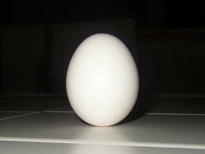
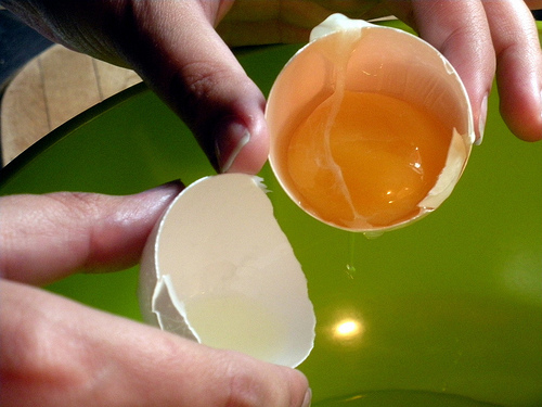
One good illustrative example of shell theory is provided by looking at an actual shell, like a chicken egg shell.  If we return to Brunelleschi, who I talked briefly about here, it is interesting to note how he convinced his patrons (Medici) to allow him to build his famous dome.  He simply took eggs and squashed their wide bottoms, so the thin tips were pointing up!  Voila! He seemed to say, the egg creates a catenary arch which is simple, robust, rigid, symmetrical and will serve as a form to make the masonry dome, or duomo.  His idea worked, it worked magnificently, and today we still have his duomo as a testament to his insight.  It is interesting to note that Brunelleschi had a highly developed intuitive sense of shell theory centuries before this theory had been mathematically expressed and articulated by equations.

If we take this example of an actual egg shell and apply some of what was learned by Galileo’s mistake of applying his Square Cube Law to masonry structures (as I discussed here, here and here) the results are pretty astounding.  The reader will recall that one critical fact of masonry arches is that they are scaleable.  This means that if an arch’s span is doubled, it will remain stable so long as the wall thickness is also doubled.  As long as proportions remain intact, a dome or arch remains stable, no matter how large it is made.  This is a direct refutation of Galileo’s Square Cube Law.  Galileo was wrong when he applied his law to masonry arches.

An actual chicken egg has a ratio of wall thickness to diameter of 7 to 1000.  In other words, an egg 2 inches across has a shell which is 0.014 inches thick.  If we “scale up” the egg so that it has a diameter of, say, 25 feet in diameter, then the walls would be only 0.175 inches thick!  This points to the inherent strength of a masonry arch which is doubly curved, or domed.  Any engineer must include a safety factor.   I am planning to make triangular block to build a 25 foot diameter dome with wall thickness of just 4 inches.  If directly compared with an egg shell, this provides an adequate safety factor of almost 23 (0.175 x safety factor = 4; safety factor = 22.857).  A typical safety factor is usually around 10.  Thus a 25 foot diameter dome made with block 4 inches thick would have a very high safety factor.  Of course block differ from eggshell, so the comparison is tricky; more on that later.

I’ll talk more about Shell Theory and masonry domes in my next entry.  This is a fascinating topic.

Thursday, January 26, 2012

The curious case of code concludes

Building code was developed to help ensure that buildings are safe.  Code has developed over time, its evolution reflects the knowledge of observed results.   

In my last two entries on this blog, I wrote about the ways in which existing Code is not practical for triangular block.  I do not intend this as a criticism of Code, or as a complaint against those who have composed our current Code.  I simply mean to point out that current Code does not account for triangular block used in innovative masonry.  Triangular block does, in fact (and indeed) meet most building Code.
I want to stress that Code is intended as a guide which is meant to help the architect, contractor, builder and working mason to design and make safer buildings.  Much leeway is provided for in Code to allow for architects, designers and builders to express their creative and innovative approaches in providing solutions to the challenges involved in making good buildings.
This flexibility in the code is even specifically addressed by the National Concrete MasonryAssociation (NCMA) in their commentary on code.  The creativity and imagination of the marketplace in designing and developing novel unitconfiguration far exceeds the ability of prescriptive national standards to keep pace. Case in point, ASTM C90 addresses the minimum physical properties for loadbearing concretemasonry units. The requirements of ASTM C90 and the companion testing standard ASTM C140 are by necessity generic in nature – applying to the majority, but not all,
configurations of units. As special or proprietary units are introduced to the market, they may not be able to be evaluated consistently or accurately under ASTM C140, or may not have all of the relevant features for strict compliance with ASTM C90.”

In concluding my brief discussions on Code, I want to look at control joints.  Control joints are included in masonry construction to allow for the expansion and contraction of a masonry wall, and to allow for movement without the wall suffering from cracks.  Control joints mean that the wall is essentially “pre-cracked” and will thus allow for movement without breaking. 

Code addresses control joints in the following (rather open-ended) manner:  “Restrained or differential movement in building elements and building materials can result in cracking. Some common causes of movement are: loads created by wind, soil pressure, seismic forces, or other external sources; settlement of foundations; or volume changes in materials. For example, volume changes in concrete masonry units can be caused by moisture gain and loss, thermal expansion and contraction, and carbonation. To limit and control cracking due to these and other causes, proper design, detailing, construction, and materials are necessary.  Specification C 90 provides a maximum limitation on the total linear drying shrinkage potential of the units, but it is not within the scope of this specification to address other design, detailing, construction, or material recommendations. This type of information and related guidelines for crack control are available from other organizations.”  [Taken from Appendix X2, NCMA commentary]

Multiple industry publications are available on the subject of crack control in concrete
masonry construction, including:

TEK 10-1A, Crack Control in Concrete Masonry Walls

TEK 10-2C, Control Joints for Concrete Masonry Walls – Empirical Method

TEK 10-3, Control Joints for Concrete Masonry Walls – Alternative Engineered Method

TEK 10-4, Crack Control for Concrete Brick and Other Concrete Masonry Veneers

While each of these documents specifies distances between control joints, none of this applies to triangular block.  This is because triangular block break differently than rectangular block.  The key to understanding this is conjugate shearing, as I discussed here and here.  Triangular block are inherently disposed to conjugate shearing, whereas rectangular block are not.  When cracks develop on rectangular block wall, the result is a weaker, less attractive –some may call it ugly- fault in the structure.  Conjugate shearing, on the other hand, does not create any visible crack at all.  Code does not account for conjugate shearing, simply because rectangular block are incapable of conjugate shearing.  Shown below is a prototype dome, which is essentially composed entirely of control joints, via conjugate shearing between triangular block.

Although I could continue, this concludes the curious case of Code regarding triangular block.

Wednesday, January 18, 2012

The curious case of code continues

Building codes are used to help ensure the safety of buildings.  If a construction system provides a safer building, this should be reflected in the building code.  The benefits of triangular block are actually reflected in the current building code, although not articulated.

In my last entry we looked at ASTM C90-11a Standard Specification for Loadbearing Concrete Masonry Units.  This code describes how concrete blocks should be made.  I discussed some of the difficulties of this code regarding triangular concrete block.

ASTM C140 - 11a “Standard Test Methods for Sampling and Testing Concrete Masonry Units and Related Units” is another bit of code that describes how to measure certain characteristics of a block (compressive strength, linear drying shrinkage, dimensions, etc.) or concrete masonry unit (CMU).  In the US, CMU are manufactured to conform to ASTM C140. 

A regular (rectangular) CMU is tested for compressive strength by placing it in a mechanism that squeezes it together until it breaks.  The direction of squeezing, or axis of compressive force, is the same direction or axis of compaction when the block is made from loose concrete.  This is the axis of highest strength in the CMU.

In a regular, vertical wall made from rectangular CMU, the high strength axis of the block is oriented in the vertical direction.  That means that the weaker axis is facing horizontally.  A concrete block wall hit or impacted from the side is much easier to break than if it were hit from the top (or bottom). 

The Federal Emergency Management Agency (FEMA) tests for tornado and hurricane survivability of concrete block wall structures by firing a 2”x4” through cannon at the side of a wall.  If block are laid with no reinforcement or pouring all hollow cores with concrete, the 2”x4”s will simply pop holes right through the walls.   The weak axis is facing the outside.

Triangular CMU’s are made with the axis of compaction, or highest strength, facing the outside.  The resulting structure is much stronger than a conventional block wall, and will readily withstand the FEMA impact test described above.  Furthermore, a spherical or dome structure is inherently stronger and more robust than a flat wall.

While the compressive strength of triangular CMU can readily be measured in existing ASTMC140, its high strength advantage over rectangular CMU is not reflected by current code.

Monday, January 16, 2012

The curious case of masonry building code for triangular block

Building code requirements can present a unique quandary to the introduction of fundamentally innovative techniques and methods in masonry construction.

A discussion of building code and innovative masonry construction begins by describing the alphabet soup of government and industry organizations involved in developing and commenting on this code.  Here are some of the major players in developing building code for masonry construction, both in the US and internationally:

ASTM (ASTMI): American Society for Testing and Materials (International)

TMS:  The Masonry Society

NCMA:  National Concrete Masonry Association

ACI:  American Concrete Institute

The requirements for concrete masonry units (block) are described in “ASTM C90 - 11a Standard Specificationfor Loadbearing Concrete Masonry Units.”  This document has evolved over the years, and is changed as industry and uses change.  It is written by committee members composed of ACI members.  This document is commented in a document produced by NCMA simply titled “NCMA Commentary Discussions to ASTM C90.”


The first difficulty lies in finding a proper classification for the block system I have developed.  Is it loadbearing or non-loadbearing?  According to ASTM et al, if a structure does not support anything other than its own weight, it is non-loadbearing.  Since my block system supports only itself, it is technically a non-loadbearing structure.  This is of course untrue, since “only itself” includes a dome or arched roof, which means that it is loadbearing.


Another difficulty lays in the fact that concrete masonry units have become standardized to such an extent that there is no allowance for a triangular-shaped masonry unit.  All masonry units are assumed to be rectangular, and are even illustrated as such within the code specification.


This rectangular bias, or prejudice, or way of assessing masonry creates a number of difficulties relative to triangular block.  Unit strength, cracking, density, appearance, water resistance (absorption), and thermal & acoustic insulation are all affected by whether or not the masonry unit is rectangular or triangular.  Fortunately, triangular block which are used to assemble into a sphere, or dome or arch are stronger, less crack prone, more water resistant; and may be made more or less dense depending on wall thickness – thus effecting insulation properties also.


Ultimately, the code is written in such a way to allow for the designer and builder to exercise their own expertise, experience, and professional judgment in their projects.  It remains a question whether or not the existing code could be modified to describe triangular block used to build spheres, domes, arches, cylinders, etc., or if a whole new section would have to be added.  I am reminded of how much I love to sit on committees. 

Thursday, January 5, 2012

Cement Production and Greenhouse Gasses


Global warming due to manmade greenhouse gasses is a major threat to our planet.  Burning fossil fuels is the main contributor to greenhouse gasses and to increased CO2 levels.  We are interrupting Nature’s Carbon Cycle, which revolves carbon between the atmosphere, water, life and the solid earth itself.   We are suddenly releasing (over decades, or a century or so) CO2 into our atmosphere which has been locked away in the earth as fossil fuels for hundreds of millions of years.  This interruption of the Carbon Cycle is having an increasing warming effect on earth’s climate.

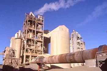
Aside from fossil fuels, other industries create CO2.  One of the largest contributors is cement production.  Cement production adds around 4% or 5% of manmade CO2 to the atmosphere globally (in the US, cement manufacture adds about 1% of CO2).  This is a big problem, and many efforts are underway to come up with cements that produce less CO2 than Portland (regular) cement.  However, this amount is not as bad as it first appears, as I try to explain below.

Cement production involves heating a mixture of rocks, clays and such until the mix undergoes a chemical change called calcining, involving thermal decomposition, phase changing, and removing the volatile compounds.  In the case of Portland cement, the main volatile compound removed is CO2, which goes right into the atmosphere. 

Once cement is mixed with aggregate and water to make concrete, it undergoes curing for a very long time.  Curing is the process of forming hydration products from the cement and water, and also absorbing CO2 from the atmosphere.   Yes, cement reclaims about60% of the CO2 it contributed to the atmosphere when it was manufactured as that same cement cures and forms hydration products.

It is important to acknowledge that cement manufacture is a major contributor to manmade greenhouse gasses, and to see the necessity of developing greener cements.  It is also important to acknowledge that concrete acts as a carbon sink once it is formed, and that most of the CO2 produced from calcinations during manufacture ultimately returns from the atmosphere into the concrete. 

In terms of CO2 that cement manufacturing and the concrete industry add to the atmosphere: it’s bad, but not as bad as it first looks.  Much of the CO2 returns from the atmosphere into curing concrete.

Sunday, January 1, 2012

Ancient Alien Masonry?

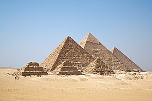
Some people propose that intelligent alien life came here (to earth) and oversaw the design and construction of great architectural works including the Great Pyramids of Egypt, Machu Picchu, and even some of the great Mayan temples.

Looking at the archaeological evidence, the history of architecture, anthropology, and countless other bodies of evidence, it is clear that all masonry structures on earth are man-made.  This work was not done by aliens.  To suggest that aliens are responsible for some of the best masonry construction diminishes some of humanity’s greatest accomplishments.

Is it possible that aliens could have visited earth and supervised construction?  Sure, anything is possible: you just need proof, there is no proof.  It is extremely improbable that aliens built the pyramids, or anything else.  It is ridiculously improbable.

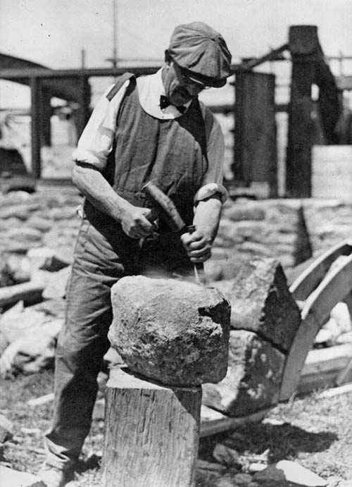
When the History Channel provides shows like Ancient Aliens, they do a disservice to early masons.  It is something of a backhanded compliment to the incredible skill, knowledge, aesthetics and abilities of ancient masons: that these shows foolishly propose ancient aliens. 

If you ponder the pyramids, or muse on Machu Picchu, or cherish Chichen Itza, then you are pondering the work of people.  Not aliens.