

Concrete is composed of different sized particles. From large aggregate (rocks) to small aggregate (sand) to paste (cement). It is important that these materials be mixed in proper proportions. If there are only large stones, there will be gaps between the stones. If there is only sand, it will not be as strong. If there is only cement paste, the material would be subject to stresses and cracking on curing (cement is also more expensive).
An ideal concrete mix is mostly large aggregate, enough small aggregate to fill the gaps between the large aggregate, and enough cement paste to bind the aggregate together. A naturally occurring mixture of rock and sand -like one might dig from a creek- is usually pretty close to the ideal mix, which is pretty fortunate. Evaluation of particle size distribution is commonly done through a sieve analysis.
Large aggregate is not usually round, or spherical. Typical aggregate (crushed stone) has a longer dimension and a shorter dimension. This results in a “tip” and a “face” on an average piece of aggregate. One of the keys to high strength concrete is tip-to-face contact between aggregate.
On the scale of small aggregate, very small aggregate is referred to as “fines” (like dust). Fines are problematic to the concrete industry. The reason is that too much fines in a mix (concrete recipe) will prevent the tip-to-face intimate consolidated structure between chunks of large aggregate which is desirable for high-strength concrete. Fines “over-stuff” the interstitial sites between aggregate and prevent tip-to-face contact between large aggregate.
Concrete manufacturers go to great lengths to reduce the amount of fines in their design mixes. The result is that there is a surplus of fines produced by concrete manufacturers. Fines are considered a waste product by the concrete/aggregate industry. The composition of fines varies depending on the composition of the parent rock, so there is a broad spectrum of composition of fines across the industry, depending on where the rock is mined.
One company has realized the value of fines produced on a national basis. This company is “Scotts,” the soil and fertilizer company. They catalog, blend, mix and sell fines from across the country. They fairly dominate this market. They have an extensive, detailed, international, comprehensive catalog of fines.
Great Scott! Does anyone have a better use for fines? There’s a big resource out there, and it appears to be underutilized.
Subscribe To
Monday, May 31, 2010
Friday, May 28, 2010
Hardened Structures (to survive Armageddon!)
Hardened structures are designed to withstand any heavy loading which may be encountered due to hurricanes, tornadoes & other severe weather events; and blasts from bombs, explosions, artillery and nuclear explosions. The masonry system described on this blog can provide hardened structures in a number of design layouts at a reasonable cost, while providing a high safety factor.
Most of us are aware of the backyard bomb shelters which were fairly common at the height of the cold war. These were typically underground structures designed to withstand a nuclear war, and would allow a family to survive the immediate blast and fallout period following a nuclear attack.

Surprisingly, there is still a large market for hardened structures which offer to help people survive such ominous threats as discussed in this article from Popular Mechanics: “The bomb shelter business is booming. At least that's the consensus of the men and women who design, construct and install underground sanctuaries. They attribute the growth in business to Kim Jong Il's erratic missile lobbing, the intransigent Iranian clerics hell-bent on getting nuclear weaponry, the impending total collapse of the global financial system, and the end of the world in 2012, as predicted by the Mayan Calendar.

"For whatever reason—and we're not totally sure ourselves—but business is incredible," Brian V. Camden, an engineer at high-end shelter builder Hardened Stuctures, says. "Twenty-twelve, the financial collapse: I just had to hire a new architect Tuesday. Right now we're doing a lot in Tennessee, Kentucky, Pennsylvania. All through Appalachia, it's people who share a similar mind-set."

The market for hardened structures is met by companies like Hardened structures of Colorado. This market segment seems to be populated by nice people. If you read their marketing material you get the feel for it.
Kim Jong Il and the Mayan calendar notwithstanding, a very real need for hardened structures is to have a safe room for tornadoes in the section of America known as “tornado alley.” Another real need for hardened structures is for any area prone to hurricanes. In an average year, 800 tornadoes are reported nationwide, resulting in 80 deaths and over 1,500 injuries. Landfalling hurricanes cause around 20 deaths per year, and around $5.2 billion in damage, according to NOAA.
The masonry system I’ve been describing can provide a high performance, economical method for building a hardened structure. A hardened structure using this design should ideally utilize the “dimp” design; it should also employ a tensile web woven into the block, and its performance is further increased by building concentric shells, one over the other, in an onion skin-like arrangement. Such a structure would be toughened (resistant to crack propagation), hardened, strengthened, robust (insensitive) and secure.
Blast-resistant structures for military and defensive applications have a unique set of parameters that they must address. This is pretty interesting stuff, and we’ll take a look at that next time.
Armageddon? I’m-a-gettin’ out of here!
Thursday, May 27, 2010
Hot Fluid Catalytic Beds
Hot fluid catalytic beds are used by industry to chemically process materials through heat, combustion and catalysis. One of the largest applications for hot fluid catalytic beds is by the fossil fuel industry, as employed by refineries which process crude oil into its component parts; from gasoline, kerosene, diesel, tar, to petroleum jelly, etc. Fluid Catalytic Cracking (FCC) is the dominant conversion process in petroleum refineries and the major contributor to “value added” in the refining process. Hot fluid catalytic beds are also used for creating fertilizers, cements and many other types of chemicals.
Here is a schematic image of a fluid bed used for cement production:

Here is a decent discussion of ‘cracking’, catalysis and fluid processes:
“The term “cracking” refers to the process through which large hydrocarbon molecules are split into smaller ones in order to obtain lighter hydrocarbons. This process requires very high temperatures and sometimes the use of a “catalyst”. In fact, there are different types of cracking. There are two types of cracking which have additional variations in the way they are implemented.
The first type of cracking is called “Thermal cracking”. It basically consists in heating the hydrocarbons until they reach high temperatures using also high pressures in some cases. This allows the hydrocarbons to break apart forming simpler hydrocarbons. The simple word “cracking” is often used to refer to this type of cracking as this is the oldest and most common type of cracking. However, thermal cracking can be achieved in different ways. There are three methods to implement thermal cracking:
• Steam - high temperature steam (1500 degrees Fahrenheit / 816 degrees Celsius) is used to break ethane, butane and naptha into ethylene and benzene, which are used to manufacture chemicals.
• Visbreaking - residual from the distillation tower is heated (900 degrees Fahrenheit / 482 degrees Celsius), cooled with gas oil and rapidly burned (flashed) in a distillation tower. This process reduces the viscosity of heavy weight oils and produces tar.
• Coking - residual from the distillation tower is heated to temperatures above 900 degrees Fahrenheit / 482 degrees Celsius until it cracks into heavy oil, gasoline and naphtha. When the process is done, a heavy, almost pure carbon residue is left (coke); the coke is cleaned from the cokers and sold.
The second type of cracking is called “Catalytic cracking” and it uses a catalyst to separate different hydrocarbons. This method of cracking generally uses zeolites as catalysts. Catalytic cracking can be also done through other catalyst such as aluminum hydrosilicate, bauxite and silica-alumina. As in the case of thermal cracking there are different methods to implement catalytic cracking:
• Fluid catalytic cracking- a hot, fluid catalyst (1000 degrees Fahrenheit / 538 degrees Celsius) cracks heavy gas oil into diesel oils and gasoline.
• Hydrocracking- similar to fluid catalytic cracking, but uses a different catalyst, lower temperatures, higher pressure, and hydrogen gas. It takes heavy oil and cracks it into gasoline and kerosene (jet fuel). Hydrocracking is basically a refining process that uses hydrogen and catalysts with relatively low temperatures and high pressures for converting middle boiling or residual material to high-octane gasoline, reformer charge stock, jet fuel, and/or high grade fuel oil. The process uses one or more catalysts, depending upon product output.
Once hydrocarbons have been cracked into smaller ones they pass through another fractional distillation column to be further distilled and to separate different components inside them.”
Here is a fluidized bed schematic for blast furnace metal production:
 Catalysts are typically placed on an inert, chemically stable, refractory material. This is typically ceramic. Before the invention of the masonry system described here on this blog, these catalytic domes were made of custom ceramic parts which were precision fit to a specific location within a dome. This is time consuming and expensive.
Here's a photograph of the outside of a hot fluid catalytic bed reactor:

The masonry system I’ve been describing is ideal for applications such as hot fluid catalytic beds. All masonry units are interchangeable, they do not have to be custom cut, they do not have to be precision fit, and are much easier to assemble. Each masonry unit can be made with a through hole, to allow for hot gas to flow through the dome. Alternatively, the masonry units can be made of porous material, so that hot gas can also flow through the dome. Finally, the “dome” can be flipped upside-down, like a bowl. This is advantageous because in a dome the gas flow tends to be higher in the center of the dome; gas flow should ideally be equal across the surface of the dome, and inverted bowl helps to achieve this sort of flow.
This masonry system provides an improved method for constructing hot fluid catalytic beds for use in several fields of chemical processing industries.
Here is a schematic image of a fluid bed used for cement production:
Here is a decent discussion of ‘cracking’, catalysis and fluid processes:
“The term “cracking” refers to the process through which large hydrocarbon molecules are split into smaller ones in order to obtain lighter hydrocarbons. This process requires very high temperatures and sometimes the use of a “catalyst”. In fact, there are different types of cracking. There are two types of cracking which have additional variations in the way they are implemented.
The first type of cracking is called “Thermal cracking”. It basically consists in heating the hydrocarbons until they reach high temperatures using also high pressures in some cases. This allows the hydrocarbons to break apart forming simpler hydrocarbons. The simple word “cracking” is often used to refer to this type of cracking as this is the oldest and most common type of cracking. However, thermal cracking can be achieved in different ways. There are three methods to implement thermal cracking:
• Steam - high temperature steam (1500 degrees Fahrenheit / 816 degrees Celsius) is used to break ethane, butane and naptha into ethylene and benzene, which are used to manufacture chemicals.
• Visbreaking - residual from the distillation tower is heated (900 degrees Fahrenheit / 482 degrees Celsius), cooled with gas oil and rapidly burned (flashed) in a distillation tower. This process reduces the viscosity of heavy weight oils and produces tar.
• Coking - residual from the distillation tower is heated to temperatures above 900 degrees Fahrenheit / 482 degrees Celsius until it cracks into heavy oil, gasoline and naphtha. When the process is done, a heavy, almost pure carbon residue is left (coke); the coke is cleaned from the cokers and sold.
The second type of cracking is called “Catalytic cracking” and it uses a catalyst to separate different hydrocarbons. This method of cracking generally uses zeolites as catalysts. Catalytic cracking can be also done through other catalyst such as aluminum hydrosilicate, bauxite and silica-alumina. As in the case of thermal cracking there are different methods to implement catalytic cracking:
• Fluid catalytic cracking- a hot, fluid catalyst (1000 degrees Fahrenheit / 538 degrees Celsius) cracks heavy gas oil into diesel oils and gasoline.
• Hydrocracking- similar to fluid catalytic cracking, but uses a different catalyst, lower temperatures, higher pressure, and hydrogen gas. It takes heavy oil and cracks it into gasoline and kerosene (jet fuel). Hydrocracking is basically a refining process that uses hydrogen and catalysts with relatively low temperatures and high pressures for converting middle boiling or residual material to high-octane gasoline, reformer charge stock, jet fuel, and/or high grade fuel oil. The process uses one or more catalysts, depending upon product output.
Once hydrocarbons have been cracked into smaller ones they pass through another fractional distillation column to be further distilled and to separate different components inside them.”
Here is a fluidized bed schematic for blast furnace metal production:
Here's a photograph of the outside of a hot fluid catalytic bed reactor:
The masonry system I’ve been describing is ideal for applications such as hot fluid catalytic beds. All masonry units are interchangeable, they do not have to be custom cut, they do not have to be precision fit, and are much easier to assemble. Each masonry unit can be made with a through hole, to allow for hot gas to flow through the dome. Alternatively, the masonry units can be made of porous material, so that hot gas can also flow through the dome. Finally, the “dome” can be flipped upside-down, like a bowl. This is advantageous because in a dome the gas flow tends to be higher in the center of the dome; gas flow should ideally be equal across the surface of the dome, and inverted bowl helps to achieve this sort of flow.
This masonry system provides an improved method for constructing hot fluid catalytic beds for use in several fields of chemical processing industries.
Tuesday, May 25, 2010
Harder, stronger, stiffer, tougher.
Today I’m taking a quick look at material properties and what exactly they mean in terms of the masonry system I’ve been describing.
Strength is defined as the ability of a material to withstand applied stress without suffering failure. As stated before on this blog, ceramics, concrete and glass have a high compressive strength.
Stiffness is defined as a measure of resistance of a material to deformation under an applied stress. Concrete and ceramics generally have a high stiffness. Stiffness is characterized by Young’s Modulus.
Hardness is defined as the measure of how resistant a material is to permanent shape change under an applied stress.
Toughness is defined as how resistant a material is to crack propagation. It is the resistance to fracture under applied stress; it is the amount of energy per unit volume that a material can absorb before rupturing.
Concrete and ceramics have a high compressive strength, a high stiffness and hardness. Concrete and ceramics are generally not very tough: they will tend to crack because of their somewhat brittle nature. The larger the item, the greater tendency to suffer cracking from applied stress. As the size increases, this tendency toward cracking increases exponentially.
The masonry system I’ve been describing is strong, stiff, hard and tough. This system gains its toughness by virtue of the fact that it is composed of relatively small unit shapes. In this sense, it is “pre-fractured” and is held together by the interlocking features. That is, a large structure is less likely to break if it is already “broken” into component parts.
The component parts in this case are masonry units which are free to move (strain) under an applied force (stress). Strain relieves stress. This results in a strong, hard and tough structure.
Monday, May 24, 2010
Retaining Walls: to make a glacier?
I just came across an interesting article in Scientific American, which describes one man’s successful effort in using retaining walls to create artificial glaciers. I thought this was quite interesting, and since I just wrote about retaining walls, figured I’d share this.

Chewang Norphel is a retired engineer who has been working with the village of Stakmo in the Himalayas. Global warming has been reducing the glaciers in the Himalayas, and many villages are entirely dependent on water which results from glacial run-off in order to live, farm, and raise livestock.
Norphel uses masonry retaining walls to divert, capture and store run-off in a sort of reservoir; so that it freezes and forms a glacier. Subsequently, the “glacier” undergoes a natural but controlled melt, and provides run-off for the needs of the villagers.

This is a fine example of appropriate technology being used. Note that all the masonry is simple stone, found on-site. A very successful, attractive and effective system which looks like it should last for a long time with simple and modest upkeep.
 Here's a great slideshow about Norphel's effort.
Masonry used for water storage will likely have a growing role globally as the need, cost and scarcity of potable water increase.

Chewang Norphel is a retired engineer who has been working with the village of Stakmo in the Himalayas. Global warming has been reducing the glaciers in the Himalayas, and many villages are entirely dependent on water which results from glacial run-off in order to live, farm, and raise livestock.
Norphel uses masonry retaining walls to divert, capture and store run-off in a sort of reservoir; so that it freezes and forms a glacier. Subsequently, the “glacier” undergoes a natural but controlled melt, and provides run-off for the needs of the villagers.

This is a fine example of appropriate technology being used. Note that all the masonry is simple stone, found on-site. A very successful, attractive and effective system which looks like it should last for a long time with simple and modest upkeep.

Masonry used for water storage will likely have a growing role globally as the need, cost and scarcity of potable water increase.
Tuesday, May 18, 2010
Retaining walls and Landscaping
Landscaping and retaining wall applications are a large market for manufactured concrete block. A number of companies offer various designs for retaining wall and landscaping applications. Many of these designs have been very successful and have established themselves as attractive options for landscapers, homeowners, businesses and municipal customers.
Here is a good discussion of retaining wall systems:
“Gravity walls depend on the weight of their mass (stone, concrete or other heavy material) to resist pressures from behind and will often have a slight 'batter' setback, to improve stability by leaning back into the retained soil. For short landscaping walls, they are often made from mortarless stone or segmental concrete units (masonry units)[6]. Dry-stacked gravity walls are somewhat flexible and do not require a rigid footing in frost areas.

Earlier in the 20th century, taller retaining walls were often gravity walls made from large masses of concrete or stone. Today, taller retaining walls are increasingly built as composite gravity walls such as: geosynthetic or with precast facing; gabions (stacked steel wire baskets filled with rocks); crib walls (cells built up log cabin style from precast concrete or timber and filled with soil); or soil-nailed walls (soil reinforced in place with steel and concrete rods).
Sheet pile retaining walls are usually used in soft soils and tight spaces. Sheet pile walls are made out of steel, vinyl or wood planks which are driven into the ground. For a quick estimate the material is usually driven 1/3 above ground, 2/3 below ground, but this may be altered depending on the environment. Taller sheet pile walls will need a tie-back anchor, or "dead-man" placed in the soil a distance behind the face of the wall, that is tied to the wall, usually by a cable or a rod. Anchors are placed behind the potential failure plane in the soil.
Cantilever wallsCantilevered retaining walls are made from an internal stem of steel-reinforced, cast-in-place concrete or mortared masonry (often in the shape of an inverted T). These walls cantilever loads (like a beam) to a large, structural footing, converting horizontal pressures from behind the wall to vertical pressures on the ground below. Sometimes cantilevered walls are butressed on the front, or include a counterfort on the back, to improve their strength resisting high loads. Buttresses are short wing walls at right angles to the main trend of the wall. These walls require rigid concrete footings below seasonal frost depth. This type of wall uses much less material than a traditional gravity wall.
An anchored retaining wall can be constructed in any of the aforementioned styles but also includes additional strength using cables or other stays anchored in the rock or soil behind it. Usually driven into the material with boring, anchors are then expanded at the end of the cable, either by mechanical means or often by injecting pressurized concrete, which expands to form a bulb in the soil. Technically complex, this method is very useful where high loads are expected, or where the wall itself has to be slender and would otherwise be too weak.”
Retaining walls are commonly used to shore up a steep slope and prevent erosion and hillside creep. Walls are typically built from stacked blocks which lock together by a number of different mechanisms and arrangements; including pins, clips, keys and the like. Usually a geotextile is used to anchor the block into the hillside which it is supporting. The geotextile is a web-like material that gets buried in the earth for some distance behind the retaining wall, to create an effective anchor with a high tensile strength. The top of a retaining wall is commonly capped with a sill or capstone block.

Retaining walls are often assembled with a slight incline from the vertical, so that they are effectively leaning back, or staggered against the earth they are supporting. They can be laid with a curvature in their footprint. This curvature may be both convex and concave, so that a serpentine effect is possible. Most retaining wall systems offer a decent amount of design flexibility.

The block system I’ve been describing makes a great retaining wall. The ability to do a spherical section, like part of a dome, or a ‘bowl’ gives a whole extra design element to the tools of the landscape architect. If the wall curves out, it is like a dome; if the wall curves in, it is like a bowl. The blocks I’ve been describing in this blog can also be woven together with a tensile element, such as steel cable, nylon rope, etc. This system creates a very high strength wall which is simple and easy to install.
Here is a good discussion of retaining wall systems:
“Gravity walls depend on the weight of their mass (stone, concrete or other heavy material) to resist pressures from behind and will often have a slight 'batter' setback, to improve stability by leaning back into the retained soil. For short landscaping walls, they are often made from mortarless stone or segmental concrete units (masonry units)[6]. Dry-stacked gravity walls are somewhat flexible and do not require a rigid footing in frost areas.
Earlier in the 20th century, taller retaining walls were often gravity walls made from large masses of concrete or stone. Today, taller retaining walls are increasingly built as composite gravity walls such as: geosynthetic or with precast facing; gabions (stacked steel wire baskets filled with rocks); crib walls (cells built up log cabin style from precast concrete or timber and filled with soil); or soil-nailed walls (soil reinforced in place with steel and concrete rods).
Sheet pile retaining walls are usually used in soft soils and tight spaces. Sheet pile walls are made out of steel, vinyl or wood planks which are driven into the ground. For a quick estimate the material is usually driven 1/3 above ground, 2/3 below ground, but this may be altered depending on the environment. Taller sheet pile walls will need a tie-back anchor, or "dead-man" placed in the soil a distance behind the face of the wall, that is tied to the wall, usually by a cable or a rod. Anchors are placed behind the potential failure plane in the soil.
Cantilever wallsCantilevered retaining walls are made from an internal stem of steel-reinforced, cast-in-place concrete or mortared masonry (often in the shape of an inverted T). These walls cantilever loads (like a beam) to a large, structural footing, converting horizontal pressures from behind the wall to vertical pressures on the ground below. Sometimes cantilevered walls are butressed on the front, or include a counterfort on the back, to improve their strength resisting high loads. Buttresses are short wing walls at right angles to the main trend of the wall. These walls require rigid concrete footings below seasonal frost depth. This type of wall uses much less material than a traditional gravity wall.
An anchored retaining wall can be constructed in any of the aforementioned styles but also includes additional strength using cables or other stays anchored in the rock or soil behind it. Usually driven into the material with boring, anchors are then expanded at the end of the cable, either by mechanical means or often by injecting pressurized concrete, which expands to form a bulb in the soil. Technically complex, this method is very useful where high loads are expected, or where the wall itself has to be slender and would otherwise be too weak.”
Retaining walls are commonly used to shore up a steep slope and prevent erosion and hillside creep. Walls are typically built from stacked blocks which lock together by a number of different mechanisms and arrangements; including pins, clips, keys and the like. Usually a geotextile is used to anchor the block into the hillside which it is supporting. The geotextile is a web-like material that gets buried in the earth for some distance behind the retaining wall, to create an effective anchor with a high tensile strength. The top of a retaining wall is commonly capped with a sill or capstone block.
Retaining walls are often assembled with a slight incline from the vertical, so that they are effectively leaning back, or staggered against the earth they are supporting. They can be laid with a curvature in their footprint. This curvature may be both convex and concave, so that a serpentine effect is possible. Most retaining wall systems offer a decent amount of design flexibility.
The block system I’ve been describing makes a great retaining wall. The ability to do a spherical section, like part of a dome, or a ‘bowl’ gives a whole extra design element to the tools of the landscape architect. If the wall curves out, it is like a dome; if the wall curves in, it is like a bowl. The blocks I’ve been describing in this blog can also be woven together with a tensile element, such as steel cable, nylon rope, etc. This system creates a very high strength wall which is simple and easy to install.
Wednesday, May 12, 2010
E.T., Dome Home!
The masonry system I’ve been describing is appropriate for building structures on the moon, other planets, and in space. This is what we’ll be looking at today.

The cost of sending any material into orbit is very high. Currently this cost is estimated at around $5,000 per pound, according to PhysOrg. If we can send less material into orbit, and instead use the materials found in space, we can greatly reduce the cost of our missions in space.
The moon has long been considered a potential base for deep space exploration. This is because the cost of leaving lunar orbit is a small fraction of the cost of leaving earth orbit; it takes a lot less energy to launch from the moon (less than 5%). Currently NASA plans to have a habitable moon base by 2024; although this plan is currently being brought under scrutiny by the Obama administration.
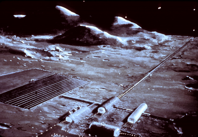
The surface of the moon is comprised of a mix of rocks, minerals and clays not entirely unlike earth. It would be possible to make masonry units from the rock and mineral mixes found on the moon. This material could be surface mined, mixed, and formed into blocks by robotic equipment. Here is an artist’s conception of lunar mining.
The block system described on this blog would lend itself readily to robotic production, due to the simple two-piece mold and ease of production. Once formed, these blocks could be fired (heat treated) by a solar kiln, where mirrors reflect and focus solar energy to provide sintering and solidification to masonry units. Alternatively, a small addition of cement-like material could help consolidate and form these blocks.
Robots could then be used to assemble a structure on the surface of the moon. The interlocking feature, together with a woven tensile element, provides a relatively simple assembly method with a robust design and high strength. A spherical section (e.g., dome) would be an ideal configuration for a lunar structure.
Once assembled, the dome would be lined with a bladder and inflated to provide a habitable structure prior to human arrival. The mineral composition of the lunar surface provides an appropriate material to block out cosmic radiation and harmful high energy particles. The high specific heat and thermal mass of this structure would greatly dampen the extreme temperature swings which occur between lunar day and night. The effects of extreme hot and extreme cold would be greatly reduced.
The unprecedented success of the robotic systems on the recent Mars Rover missions indicates that robotic units are capable of performing adequately when asked to perform rather sophisticated maneuvers and manipulations. Honeybee Robotics was involved in developing and deploying these robotic systems on the Mars missions. I have begun preliminary conversations with their engineers on my approach, they seem interested.
Aside from the moon and a similar sort of deployment on Mars, this masonry system could also be used to build self-contained satellites as complete spheres. These could be made for near earth orbit, for “way stations” throughout our solar system, to store material such as fuel, water and oxygen. They could also be placed on larger asteroids in the asteroid belt, such as 253 Mathilde.
This masonry system provides a compelling set of reasons for its deployment in extraterrestrial applications. First, we greatly reduce the cost of sending material into orbit from earth. Secondly, it can be made using the materials found on the moon, Mars, etc. Third, it can be produced and assembled robotically. Finally, this system blocks out harmful cosmic radiation, takes advantage of the high thermal mass to dampen out extreme temperature fluctuations, and provides an appropriate architectural shell for housing a bladder, to provide a suitable atmosphere for human habitation.
Next time we’ll take a look at retaining walls and landscaping applications for this block system. This is a very large and growing market for masonry units.
The cost of sending any material into orbit is very high. Currently this cost is estimated at around $5,000 per pound, according to PhysOrg. If we can send less material into orbit, and instead use the materials found in space, we can greatly reduce the cost of our missions in space.
The moon has long been considered a potential base for deep space exploration. This is because the cost of leaving lunar orbit is a small fraction of the cost of leaving earth orbit; it takes a lot less energy to launch from the moon (less than 5%). Currently NASA plans to have a habitable moon base by 2024; although this plan is currently being brought under scrutiny by the Obama administration.
The surface of the moon is comprised of a mix of rocks, minerals and clays not entirely unlike earth. It would be possible to make masonry units from the rock and mineral mixes found on the moon. This material could be surface mined, mixed, and formed into blocks by robotic equipment. Here is an artist’s conception of lunar mining.
The block system described on this blog would lend itself readily to robotic production, due to the simple two-piece mold and ease of production. Once formed, these blocks could be fired (heat treated) by a solar kiln, where mirrors reflect and focus solar energy to provide sintering and solidification to masonry units. Alternatively, a small addition of cement-like material could help consolidate and form these blocks.
Robots could then be used to assemble a structure on the surface of the moon. The interlocking feature, together with a woven tensile element, provides a relatively simple assembly method with a robust design and high strength. A spherical section (e.g., dome) would be an ideal configuration for a lunar structure.
Once assembled, the dome would be lined with a bladder and inflated to provide a habitable structure prior to human arrival. The mineral composition of the lunar surface provides an appropriate material to block out cosmic radiation and harmful high energy particles. The high specific heat and thermal mass of this structure would greatly dampen the extreme temperature swings which occur between lunar day and night. The effects of extreme hot and extreme cold would be greatly reduced.
The unprecedented success of the robotic systems on the recent Mars Rover missions indicates that robotic units are capable of performing adequately when asked to perform rather sophisticated maneuvers and manipulations. Honeybee Robotics was involved in developing and deploying these robotic systems on the Mars missions. I have begun preliminary conversations with their engineers on my approach, they seem interested.
Aside from the moon and a similar sort of deployment on Mars, this masonry system could also be used to build self-contained satellites as complete spheres. These could be made for near earth orbit, for “way stations” throughout our solar system, to store material such as fuel, water and oxygen. They could also be placed on larger asteroids in the asteroid belt, such as 253 Mathilde.
This masonry system provides a compelling set of reasons for its deployment in extraterrestrial applications. First, we greatly reduce the cost of sending material into orbit from earth. Secondly, it can be made using the materials found on the moon, Mars, etc. Third, it can be produced and assembled robotically. Finally, this system blocks out harmful cosmic radiation, takes advantage of the high thermal mass to dampen out extreme temperature fluctuations, and provides an appropriate architectural shell for housing a bladder, to provide a suitable atmosphere for human habitation.
Next time we’ll take a look at retaining walls and landscaping applications for this block system. This is a very large and growing market for masonry units.
Tuesday, May 11, 2010
Arch designs: Corbels and Catenaries
We’re taking another small detour from description of applications for the masonry system I’ve developed to talk about some fundamental aspects of masonry. Yesterday we looked at thermal mass, today we’ll take a look at types of arches; another important aspect to this masonry system.
Very early in the development of masonry in the ancient world, masons developed what is known as a corbel arch. A corbel arch is not a “true” arch because it uses blocks that are cantilevered, and do not transfer the load directly down the arch. Corbelled arches are found in ancient Irish, India, Mayan, Greek, and Cambodian architecture.

Here’s a good description of corbelled arches from Wikipedia:
“A corbel arch (or corbeled / corbelled arch) is an arch-like construction method which uses the architectural technique of corbeling to span a space or void in a structure, such as an entranceway in a wall or as the span of a bridge. A corbel vault uses this technique to support the superstructure of a building's roof.
A corbel arch is constructed by offsetting successive courses of stone at the springline of the walls so that they project towards the archway's center from each supporting side, until the courses meet at the apex of the archway (often capped with flat stones). For a corbeled vault covering the technique is extended in three dimensions along the lengths of two opposing walls.
Although an improvement in load-bearing efficiency over the post and lintel design, corbeled arches are not entirely self-supporting structures, and it is sometimes termed a "false arch" for this reason. Unlike "true" arches, not all of the structure's tensile stresses caused by the weight of the superstructure are transformed into compressive stresses. Corbel arches and vaults require significantly thickened walls and an abutment of other stone or fill to counteract the effects of gravity, which otherwise would tend to collapse each side of the archway inwards.”
A much better arch design is a catenary arch. “Catena” is Latin for “chain.” If a chain is allowed to hang with some slack, and if the links of the chain are welded together and the chain is flipped upside down, the resulting curve is a catenary curve.
Here’s a good discussion of catenary from Wolfram Mathworld:
“In 1669, Jungius disproved Galileo's claim that the curve of a chain hanging under gravity would be a parabola (MacTutor Archive). The curve is also called the alysoid and chainette. The equation was obtained by Leibniz, Huygens, and Johann Bernoulli in 1691 in response to a challenge by Jakob Bernoulli.
Huygens was the first to use the term catenary in a letter to Leibniz in 1690, and David Gregory wrote a treatise on the catenary in 1690 (MacTutor Archive). If you roll a parabola along a straight line, its focus traces out a catenary. As proved by Euler in 1744, the catenary is also the curve which, when rotated, gives the surface of minimum surface area (the catenoid) for the given bounding circle.”
Catenary arches are the strongest possible arch under gravity. Catenary arches are commonly used in gas-fired kilns. They are found across many cultures and civilizations around the world. An interesting example is Musgum architecture found in Cameroon, Africa. These beautiful structures seem naturally derived, and are a fine example of using this optimal arch design to build houses.

 If a slack chain is allowed to settle into a shape approximating a spherical curve, it gets pretty close. Thus a spherical dome is not too far from a catenary arch, and provides some indication that a spherical section is a strong arrangement.
In an environment with little or no gravity, the advantages of a catenary arch disappear, and a spherical structure stands alone as the strongest and best design for a shelled structure.
This opens the door to extraterrestrial applications, which we’ll be looking at tomorrow. Sounds like science fiction, but it’s really not.
Very early in the development of masonry in the ancient world, masons developed what is known as a corbel arch. A corbel arch is not a “true” arch because it uses blocks that are cantilevered, and do not transfer the load directly down the arch. Corbelled arches are found in ancient Irish, India, Mayan, Greek, and Cambodian architecture.

Here’s a good description of corbelled arches from Wikipedia:
“A corbel arch (or corbeled / corbelled arch) is an arch-like construction method which uses the architectural technique of corbeling to span a space or void in a structure, such as an entranceway in a wall or as the span of a bridge. A corbel vault uses this technique to support the superstructure of a building's roof.
A corbel arch is constructed by offsetting successive courses of stone at the springline of the walls so that they project towards the archway's center from each supporting side, until the courses meet at the apex of the archway (often capped with flat stones). For a corbeled vault covering the technique is extended in three dimensions along the lengths of two opposing walls.
Although an improvement in load-bearing efficiency over the post and lintel design, corbeled arches are not entirely self-supporting structures, and it is sometimes termed a "false arch" for this reason. Unlike "true" arches, not all of the structure's tensile stresses caused by the weight of the superstructure are transformed into compressive stresses. Corbel arches and vaults require significantly thickened walls and an abutment of other stone or fill to counteract the effects of gravity, which otherwise would tend to collapse each side of the archway inwards.”
A much better arch design is a catenary arch. “Catena” is Latin for “chain.” If a chain is allowed to hang with some slack, and if the links of the chain are welded together and the chain is flipped upside down, the resulting curve is a catenary curve.
Here’s a good discussion of catenary from Wolfram Mathworld:
“In 1669, Jungius disproved Galileo's claim that the curve of a chain hanging under gravity would be a parabola (MacTutor Archive). The curve is also called the alysoid and chainette. The equation was obtained by Leibniz, Huygens, and Johann Bernoulli in 1691 in response to a challenge by Jakob Bernoulli.
Huygens was the first to use the term catenary in a letter to Leibniz in 1690, and David Gregory wrote a treatise on the catenary in 1690 (MacTutor Archive). If you roll a parabola along a straight line, its focus traces out a catenary. As proved by Euler in 1744, the catenary is also the curve which, when rotated, gives the surface of minimum surface area (the catenoid) for the given bounding circle.”
Catenary arches are the strongest possible arch under gravity. Catenary arches are commonly used in gas-fired kilns. They are found across many cultures and civilizations around the world. An interesting example is Musgum architecture found in Cameroon, Africa. These beautiful structures seem naturally derived, and are a fine example of using this optimal arch design to build houses.


In an environment with little or no gravity, the advantages of a catenary arch disappear, and a spherical structure stands alone as the strongest and best design for a shelled structure.
This opens the door to extraterrestrial applications, which we’ll be looking at tomorrow. Sounds like science fiction, but it’s really not.
Monday, May 10, 2010
Thermal Mass Benefits of Masonry
Concrete, ceramics and glass all have a relatively high thermal mass. Thermal mass imparts benefits to the thermal efficiency of a structure; this is what we’ll be looking at today.
“Specific heat” is the term engineers use to describe how much heat a given material can store. In other words, how much heat is required to raise the temperature of the material. The more heat required to warm up the material, the higher its specific heat.
This is important because thermal mass is a property that enables building materials to absorb, store, and later release significant amount of heat. For example, if a stone is sitting out in the sun all day, it will collect heat from the sun and remain warm for some time after the sun goes down (and everything around it cools off) owing to the high specific heat of the stone.
Here is a good discussion of thermal mass benefits of concrete, taken from this article.
“Buildings constructed of concrete and masonry have a unique energy-saving advantage because of their inherent thermal mass. These materials absorb energy slowly and hold it for much longer periods of time than do less massive materials. This delays and reduces heat transfer through a thermal mass building component, leading to three important results.
1. There are fewer spikes in the heating and cooling requirements, since mass slows the response time and moderates indoor temperature fluctuations.
2. A massive building uses less energy than a similar low mass building due to the reduced heat transfer through the massive elements.
3. Thermal mass can shift energy demand to off-peak time periods when utility rates are lower. Since power plants are designed to provide power at peak loads, shifting the peak load can reduce the number of power plants required.
The thermal mass of concrete has the following benefits and characteristics:
Delays peak loads
Reduces peak loads
Reduces total loads in many climates and locations
Works best in commercial building applications
Works well in residential applications
Works best when mass is exposed on the inside surface
Works well regardless of the placement of mass
 Mass works well in commercial applications by delaying the peak summer load, which generally occurs around 3:00 pm to later when offices begin to close. As a case in point, the blackout in the Northeast in August 2003 occurred at 3:05 pm. A shift in peak load would have helped alleviate the demand and possibly alleviated this peak power problem.
Damping and lag effect of thermal mass
The ASHRAE Standard 90.1–Energy Standard for Buildings Except Low-Rise Residential Buildings, the International Energy Conservation Code, and most other energy codes recognize the benefits of thermal mass and require less insulation for mass walls.
In some climates, thermal mass buildings have better thermal performance than low mass buildings, regardless of the level of insulation in the low mass building. The most energy is saved when significant reversals in heat flow occur within a wall during the day. So, mass has the greatest benefit in climates with large daily temperature fluctuations above and below the balance point of the building (55 to 65°F). For these conditions, the mass can be cooled by natural ventilation during the night, and then be allowed to absorb heat or "float" during the warmer day. When outdoor temperatures are at their peak, the inside of the building remains cool, because the heat has not yet penetrated the mass. Although few climates are this ideal, thermal mass in building envelopes will still improve the performance in most climates. Often, the benefits are greater during spring and fall, when conditions most closely approximate the "ideal" climate described above. In heating-dominated climates, thermal mass can be used to effectively collect and store solar gains or to store heat provided by the mechanical system to allow it to operate at off-peak hours.
Thermal resistance (R-values) and thermal transmittance (U-factors) do not take into account the effects of thermal mass, and by themselves, are inadequate in describing the heat transfer properties of construction assemblies with significant amounts of thermal mass. Only computer programs such as DOE-2 and EnergyPlus that take into account hourly heat transfer on an annual basis are adequate in determining energy loss in buildings with mass walls and roofs. The heat flow through the wall is dependent on the materials’ unit weight (density), thermal conductivity, and specific heat.
Specific heat is defined as the amount of heat energy (in Btu) required to raise the temperature of one pound of a material by one degree Fahrenheit. Specific heat describes a material's ability to store heat energy. The specific heat of concrete and masonry can generally be assumed to be 0.2Btu/lb•°F. (ASHRAE Handbook of Fundamentals, 2005)
Heat Capacity (HC) is the amount of heat energy required to raise the temperature of a mass one degree Fahrenheit. Heat capacity is per square foot of wall area (Btu/ft2•°F) and includes all layers in a wall. For a single layer wall, HC is calculated by multiplying the density of the material times its thickness (in ft) times the specific heat of the material. HC for a multilayered wall is the sum of the heat capacities for each layer.
Values of heat capacity, thermal resistance, and thermal transmittance for concrete and masonry are presented in Appendix A of ASHRAE Standard 90.1-2004. Thermal conductivities are presented in the ASHRAE Handbook of Fundamentals.”
It should be noted that thermal mass benefits are maximized when a concrete structure is insulated on the outside. This helps store and retain heat in the thermal mass of the building. The structures I’ve built used blue-board (a type of Styrofoam) on the outside of the concrete. This blue-board was then clad with a simple wooden board & batten; any other material could also be used (clapboard, shingles, siding, etc.). Insulating the inside of the building prevents the full benefits of thermal mass from being realized, because the concrete is prevented from absorbing and releasing heat to the inside of the structure.
The thermal mass benefits of concrete result in a much more thermally efficient structure which requires significantly less energy to heat and cool. My own structures stay warm in the winter and cool in the summer, it is really quite noticeable, and my utility bills stay quite low.
“Specific heat” is the term engineers use to describe how much heat a given material can store. In other words, how much heat is required to raise the temperature of the material. The more heat required to warm up the material, the higher its specific heat.
This is important because thermal mass is a property that enables building materials to absorb, store, and later release significant amount of heat. For example, if a stone is sitting out in the sun all day, it will collect heat from the sun and remain warm for some time after the sun goes down (and everything around it cools off) owing to the high specific heat of the stone.
Here is a good discussion of thermal mass benefits of concrete, taken from this article.
“Buildings constructed of concrete and masonry have a unique energy-saving advantage because of their inherent thermal mass. These materials absorb energy slowly and hold it for much longer periods of time than do less massive materials. This delays and reduces heat transfer through a thermal mass building component, leading to three important results.
1. There are fewer spikes in the heating and cooling requirements, since mass slows the response time and moderates indoor temperature fluctuations.
2. A massive building uses less energy than a similar low mass building due to the reduced heat transfer through the massive elements.
3. Thermal mass can shift energy demand to off-peak time periods when utility rates are lower. Since power plants are designed to provide power at peak loads, shifting the peak load can reduce the number of power plants required.
The thermal mass of concrete has the following benefits and characteristics:
Delays peak loads
Reduces peak loads
Reduces total loads in many climates and locations
Works best in commercial building applications
Works well in residential applications
Works best when mass is exposed on the inside surface
Works well regardless of the placement of mass

Damping and lag effect of thermal mass
The ASHRAE Standard 90.1–Energy Standard for Buildings Except Low-Rise Residential Buildings, the International Energy Conservation Code, and most other energy codes recognize the benefits of thermal mass and require less insulation for mass walls.
In some climates, thermal mass buildings have better thermal performance than low mass buildings, regardless of the level of insulation in the low mass building. The most energy is saved when significant reversals in heat flow occur within a wall during the day. So, mass has the greatest benefit in climates with large daily temperature fluctuations above and below the balance point of the building (55 to 65°F). For these conditions, the mass can be cooled by natural ventilation during the night, and then be allowed to absorb heat or "float" during the warmer day. When outdoor temperatures are at their peak, the inside of the building remains cool, because the heat has not yet penetrated the mass. Although few climates are this ideal, thermal mass in building envelopes will still improve the performance in most climates. Often, the benefits are greater during spring and fall, when conditions most closely approximate the "ideal" climate described above. In heating-dominated climates, thermal mass can be used to effectively collect and store solar gains or to store heat provided by the mechanical system to allow it to operate at off-peak hours.
Thermal resistance (R-values) and thermal transmittance (U-factors) do not take into account the effects of thermal mass, and by themselves, are inadequate in describing the heat transfer properties of construction assemblies with significant amounts of thermal mass. Only computer programs such as DOE-2 and EnergyPlus that take into account hourly heat transfer on an annual basis are adequate in determining energy loss in buildings with mass walls and roofs. The heat flow through the wall is dependent on the materials’ unit weight (density), thermal conductivity, and specific heat.
Specific heat is defined as the amount of heat energy (in Btu) required to raise the temperature of one pound of a material by one degree Fahrenheit. Specific heat describes a material's ability to store heat energy. The specific heat of concrete and masonry can generally be assumed to be 0.2Btu/lb•°F. (ASHRAE Handbook of Fundamentals, 2005)
Heat Capacity (HC) is the amount of heat energy required to raise the temperature of a mass one degree Fahrenheit. Heat capacity is per square foot of wall area (Btu/ft2•°F) and includes all layers in a wall. For a single layer wall, HC is calculated by multiplying the density of the material times its thickness (in ft) times the specific heat of the material. HC for a multilayered wall is the sum of the heat capacities for each layer.
Values of heat capacity, thermal resistance, and thermal transmittance for concrete and masonry are presented in Appendix A of ASHRAE Standard 90.1-2004. Thermal conductivities are presented in the ASHRAE Handbook of Fundamentals.”
It should be noted that thermal mass benefits are maximized when a concrete structure is insulated on the outside. This helps store and retain heat in the thermal mass of the building. The structures I’ve built used blue-board (a type of Styrofoam) on the outside of the concrete. This blue-board was then clad with a simple wooden board & batten; any other material could also be used (clapboard, shingles, siding, etc.). Insulating the inside of the building prevents the full benefits of thermal mass from being realized, because the concrete is prevented from absorbing and releasing heat to the inside of the structure.
The thermal mass benefits of concrete result in a much more thermally efficient structure which requires significantly less energy to heat and cool. My own structures stay warm in the winter and cool in the summer, it is really quite noticeable, and my utility bills stay quite low.
Friday, May 7, 2010
Glass Block: a new design
The block system described in this blog readily lends itself to being made with glass. Today we’ll take a look at glass block, and how it would be suitable for this masonry system.
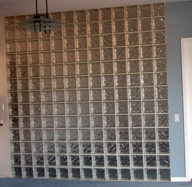 Glass block has become a fairly widespread construction material. As with concrete block, glass block are currently limited to square and rectangular blocks. This limits the architectural applications of glass block to straight vertical walls and square corners. Some block designs include curved corners, but currently no glass block can be used for spherical or dome sections, as I’m proposing here. It’s interesting to me how regular glass block today says “1980’s” and is not considered current, or ‘in vogue.’
 Glass block is manufactured by first forming two pieces of glass, and then joining them while the glass is still warm enough to be moveable (at around 800 degrees F). The two pieces are pinched together in a two-piece mold and allowed to anneal, or cool slowly to reduce thermal stresses and obtain a thermally stable object. If the hot glass is not properly annealed, it will crack some time after it is removed from heat.

Hollow glass block creates a decent thermal insulator, and saves heating and cooling requirements for a given building.
Interestingly (perhaps counter-intuitively) glass has a high strength: higher than concrete in some cases. The theoretical strength of glass is very high, and is only reduced by small surface flaws which create starting points for cracks to begin and significantly lowers the actual strength of glass.
Glass can be greatly strengthened by using a technique called ‘ion substitution.’ Glass typically is made with a flux agent, which lowers the melting temperature of the glass. Sodium is a common flux, and is typically found in silicate glasses. If a sodium silicate glass is immersed in a heated bath, comprised of (for example) potassium compounds (e.g. KOH), then the potassium will migrate into the glass, and replace sodium. Potassium is larger (ionic radius) than sodium, so it ‘stuffs’ the glass and creates compression in the glass; resulting in a much stronger glass. This method could be used to create very high strength architectural glass block.
The block system I’ve been describing in this blog is made on a two-piece mold, without any undercut. This is what is required to make hollow glass block. The block system I’ve been describing is appropriate and suitable for producing hollow architectural block.
The glass block produced from this masonry system can be used to assemble spheres, domes, arches, straight walls, and various combinations of these architectural elements. These blocks will all interlock, they are disposed to conjugate shearing without breaking, they can use a series of tensile elements (e.g., steel cable, Kevlar, etc.) to provide a much higher strength to the entire structure.
Glass block can also be used together with concrete block. This is important because glass block is more expensive than concrete, so it can be used as a highlight feature, and bring some dramatic lighting elements to an overall structure. Glass block can also be used to build a small dome, which could be incorporated as a cupola, or an architectural feature within a building. Imagine a glass dome at the top of a foyer or entryway into a building or house.
The symmetry and hexagonal elements inherent to this masonry system produces a ‘snowflake’ effect, where the architecture has a close resemblance to the beauty and symmetry found in snowflakes.
Thursday, May 6, 2010
Light in concrete


This is an interesting addition to masonry, use of light, and creation of innovative architectural design elements.

The block system I’ve been describing here is amenable to using this fiber optic technology in concrete casting. This creates some exciting possibilities.
Tuesday, May 4, 2010
Kilns and furnaces
We’re back looking at applications for this block system. So far we’ve looked at architectural applications, water storage tanks, desalination spheres and (possibly?) oil spill containment methods. Today we’ll look at kilns and furnaces.
 Kilns and furnaces made with this system offer the benefit of a radial design. Whether a sphere or a cylinder, a radial design uses less surface area per unit volume than any rectangular or square arrangement. A sphere provides the minimum surface area to volume ratio possible.
 This is important because surface area is how heat is lost to the outside: by conduction, convection and radiation cooling. If we minimize surface area, we minimize heat loss.
Furthermore, if combustion is used to heat the kiln/furnace (as opposed to electrical heating) then a round structure greatly increases the efficiency of combustion. This is done by extending the flame path in the firing space. When the flame path is extended, the chemical reaction of combustion (combining fuel with oxygen) is more thoroughly accomplished. Combustion in a round kiln (or furnace) produces a swirling vortex, a “whirl wind” of burning flame. This vortex is how the flame path gets extended in the firing space. It also creates a much more even temperature within the firing space. A square or rectangular kiln will create “hot spots” where the flame impinges on walls and corners; it also creates cool spots where the flame is less evenly applied. In the kilns I built, I used a 'downdraft' design, where combusted fuel is vented out the bottom of the kiln.
By using simple unit shapes, as described earlier in this blog, the cost of constructing a kiln is minimized. Blocks do not need to be custom cut and precision matched to their specific location: blocks are interchangeable.

I received two awards from the New York State Energy Research & Development Authority (NYSERDA) to build and test large scale kilns using this design. I built a standard rectangular kiln of the same volume, same wall thickness, same burners, etc. for the purpose of comparison. The round kiln was 37% more efficient than the rectangular kiln, and demonstrated a much more even temperature distribution. In the rectangular kiln, temperature varied by as much as 120 degrees F; within the round kiln temperature varied by only 5 degrees (at 2,300 degrees). Even temperature distribution is important to industry, where items should all be fired at the same temperature.
This technology can be used to fire ceramics, to make glass, for heat treating wood (kiln drying), and any other processes that require heat treatment. The same principals make this system appropriate for a number of consumer goods: including ovens, barbeques, smokers, etc.
Next time we’ll take a look at glass block, and how this masonry system can be used with glass block.
Monday, May 3, 2010
To fix an oil spill?
How to cap a leaking oil well at 5,000 feet below sea level?
Here’s what BP has in mind.
Their dome isn’t really a dome at all; it’s a rectangular strong box with a vent at the top. It has what they call “mud flaps” to help seal the device to the ocean floor.
The block system I’ve been describing could be used for this application.
First, it would be critical to use the ‘dimp’ design, with appropriate tensile elements (e.g. steel cable, carbon fiber) woven into the structure. It is necessary to have sufficient strength from inside pressure to hold the dome together.
Second, it would be important to have concentric shells of domes, each using the ‘dimp’ design, arranged like layers of an onion. This configuration greatly increases the strength of the dome from inside pressure which could cause a blow out. Each layer of concentric block must be woven together with the tensile elements which ‘dimp’ design allows for. Each concentric shell staggers the joints, to maximize toughness.
Third, the dome must be sufficiently anchored to the ocean floor. This could be done with proper foundation elements using piles driven into the bedrock. The tensile elements of the domes would be anchored to these piles.
Finally, Proper choice of high-strength concrete is critical. We could specify HPC’s (high performance concretes) with strengths in the range of 20,000-30,000 psi, and tensile elements with appropriate strengths. A bladder or series of bladders (“onion skins”, between concentric spheres) could be used. These could be Kevlar, carbon fiber, etc.
This dome structure would be assembled on land, shipped to site and sunk, using robotics at depth to achieve anchoring and footing.
I contacted BP and steered them to this very blog.
Let’s hope we come up with a solution fast. Maybe this might help.
Subscribe to:
Posts (Atom)