Friday, March 30, 2012

Review of Fukushima Daiichi nuclear disaster

Previously on this blog I’ve written about the nuclear disaster at Fukushima Daiichi which occurred following the earthquake and tsunami on 3/11/11; here, here and here.  Just as the US has its 9/11 tragedy, so too Japan has its 3/11 tragedy. 
 
I proposed a solution for containment and protection of the nuclear reactors at Fukushima based on a masonry system used to construct containment/protection domes around these damaged reactors.  There are many advantages to this system over competing approaches.  Today (3/30/12) a new report has been issued which outlines some of the hazards and inherent dangers present at Fukushima and their continuing threat.
As I said earlier, this danger will exist for a very long time to come.  The press has previously reported (12/11) that the Fukushima site is stabilized and that any danger or threat from these damaged reactors is essentially under control.  As today’s report shows, this danger is not stabilized and the threat from these damaged reactors remains high, and will remain high for a very long time (just like I said earlier).

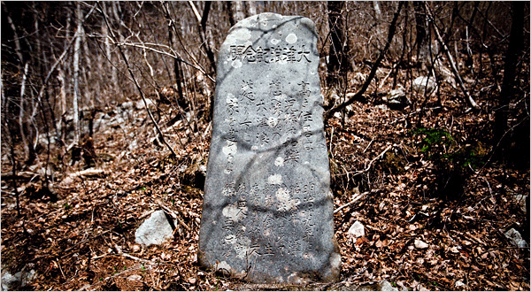
Tokyo Electric Power (Tepco) has seriously mishandled this situation since before it began.  They disregarded Japan’s own history of previous tsunamis, even though gigantic stone markers ("tsunami stones") were left in the area, hundreds of years ago, warning inhabitants:  “DO NOT BUILD HERE.”  The refusal of Tepco to acknowledge the extremely dangerous conditions at Fukushima for months after the accident further illustrate the poor management at Tepco.  Japanese society and culture place a high value on honor and integrity, yet Tepco has acted with a lack of honor and integrity throughout this crisis.  As I wrote in an earlier entry, Tepco was at one point trying to stuff the cracks in its poorly made containment structures with wet newspaper and diaper material.  Wet newspaper and diapers to control lethal radiation!
With today’s report on the state of the Fukushima’s damaged nuclear reactors, I am revisiting this topic.  My previous blog entries on Fukushima have been viewed over 5,000 times.  I wonder if anyone from Tepco, or Japan, or Westinghouse, or General Electric has read these entries?   At one point I was approached by a western consortium that had put together a comprehensive plan for clean-up and relief of Japan following the tsunami.  They asked to use my system.  Nothing ever came of it: the principals said Japan is seeking to fix its own problems largely on its own.  In terms of making Fukushima safe, they have not done so.  There is much to be done before Fukushima is stable, or safe, or manageable over a long time frame.
With today’s entry I am attempting to remind any reader that the masonry system described in this blog could be an effective, affordable, manageable method to help increase the safety at Fukushima for a very long time.
The advantages of the masonry system I propose are outlined here in summary form:
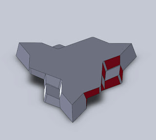
·         Mass production of the interlocking triangular masonry units allows them to be made as an engineered system at low cost, in high volume, in a short time, using existing concrete block manufacturing equipment.  The infrastructure to produce this system already exists.

·         Use of Boron-based material in the concrete mix will act to absorb radiation.  This is an existing practice in the nuclear industry; it is a known and established material and method to help control radiation.

·         Use of concentric shells in a dome structure will greatly increase the safety factor of the domed structure.  Additional layers, or wythes of brick are easy to add, and increase the safety with each subsequent layer of block.

·         The articulated shape of the masonry unit makes it inherently easy for robotic assembly.  Multiple contact guiding surfaces align the block, and allow them to simply slide together where they are effectively locked into position.

·         A spherical dome is the strongest and most robust configuration possible for this application.  In terms of an exterior applied force, is stronger than a catenary arch, and will act not only as a containment structure, but will also protect the reactors from any other tsunamis, typhoons, terror attacks and the like.

·         I have developed an automated method for placing mortar between blocks in a dome.  This would be very easy to do robotically (this method is not described here, it’s proprietary).

·         Producing masonry units at a manufacturing plant allows Quality Control which is simply not possible if wet concrete is poured on-site at a radioactive, damaged reactor facility.  As an example of poor QC, see the current state of the sarcophagus at Chernobyl.  There are now holes in it large enough to drive a car through.

·         Venting channels to help relieve the high pressures resulting from any explosion inside the reactor are readily provided in a domed containment structure.  These vents are typically filled with boron-based sand or aggregate, and activated carbon.  This sand, aggregate and activated carbon remove radioactive material from explosive gasses as they pass through the venting channel, before they vent to the outside atmosphere.

If anyone reading this is working on fixing the situation at Fukushima (or knows people who are) I urge you to contact me.  There is much more to this system than what I have described here.  I am eager to help if I can in any way.  Please feel free to contact me.

Sunday, March 11, 2012

Reintroduction

Two years ago today I began writing this blog.  Here is my first enry:

"I'm a masonry designer developing novel masonry systems for new applications. This blog will describe what my ideas are, how I'm making them, various uses, and so on. I will share ideas and hope to get feedback from as many interested people as I can.

I'm especially interested in doing more with concrete block than is currently possible. I want to expand the architectural vocabulary of concrete block construction to include much more than straight vertical walls and square corners. This is pretty much the status quo with current block design and construction.

As a child I had the good fortune of seeing some of the great cathedrals of europe. This experience left an indelible impression on me. It's probably why I do what I do; masonry architecture can be so much more than rectangular block and vertical walls.
Arch, cylinder, dome and sphere should all be part of the masonry repertoire.   This is possible with block manufacturing methods and materials, through innovative design. 
This is an exciting realm that combines ages-old building methods with current scientific & engineering knowledge and high-efficiency production methods."
Two years later the excitement continues.  Innovation in an ages-old practice like masonry means you're always bumping into ghosts of almost forgotten, basic truths.   To be aware of historical development strengthens this innovation.
One year ago today Japan was devastated by a tsunami.  May we all remember, and bear this history.

Friday, March 9, 2012

Geodesic frequencies and masonry domes


Geodesic domes are made in various “frequencies”, or “orders.”  As discussed earlier, geodesics are typically made of regular polyhedra.  The polygons which comprise these polyhedra can be broken down into their constituent basic or unit triangular shapes.  These unit or base triangles can be further subdivided into smaller triangles.  These smaller triangles can be further subdivided into still smaller triangles, etc., ad infinitum.  Each progressive division is a “frequency.”

This sort of triangular subdivision is illustrated in the Sierpinski fractal.

Higher frequency geodesics allow a large dome to be made from a relatively small unit shape.

Each time the size of a dome (radius) is doubled, the surface area is increased by a factor of 4.  This means that a dome twice as big will need 4 times as many blocks.  This reflects Galileo’s Square Cube Law.  Thus doubling the size of a dome uses 4 times as many bricks (surface area is squared) and increases the volume by a factor of 8 (the volume is cubed).  Using 4 times as many bricks creates 8 times as much volume; this is very efficient.

There are some difficulties with higher frequency geodesics.  This is due to the difference between chord length and arc length.  Arc length (S, below) refers to the measurement of the curved surface of a sphere.  Chord length (l, below) refers to the straight line distance between two points on the surface of a sphere.  Arc length is longer than chord length as measured between two points on a sphere.  If a triangle projected onto a spherical surface is broken down into smaller and smaller triangles, then a number of different sized triangles will result.  They are not all the same; there is a maddeningly large number of different dimensions for various triangles.  Historically this has been a challenge for higher order geodesics, often resulting in weakened, leaky or poorly assembled domes. 

Mortar (or gaskets) fixes this problem easily.  The differences in size are accounted for by using more or less mortar (or gasket) between block.  It is a simple matter of aligning block within their geodesic pattern.

Higher frequency domes result in a change in proportions of block.  Because the block are assembling into a larger structure, the wall also gets thicker.  This occurs proportionally: if a structure is twice as big, its walls will be twice as thick.  The result is that unit triangular shapes look less like a thin plate or shell, and more like a thick block.  The thickness is around equal to edge length.  Higher frequency blocks are more “blocky.”  This is advantageous for ceramics or concrete to bear their compressive load.  A block bears compressive load better than a thin plate.

Friday, March 2, 2012

Thickness of dome walls

Thrust force lines must be kept within wall thickness for a structure to remain standing; this makes wall thickness critically important.  The triangular interlocking masonry system described on this blog can provide different wall thicknesses through different techniques.
 
A spherical dome under gravity is subject to "hoop" stress (like lines of latitude, horizontal) which varies from the crown down to the bottom edge. This stress is completely under compression from the top center down to the haunch (51.820 from vertical).  Below the haunch there are tensile forces pushing out, which grow stronger and tend to introduce cracks at the bottom of the masonry dome.  These tensile hoop forces at the bottom of a masonry dome are typically resolved by either a tension ring, or a massive abutment, or both.

Historically masonry analysis refers to “lunes” which are like the sliced sections of an orange peel.  Each lune is viewed as a discreet arch section for the purpose of stress analysis.  From the top of the lune down to the base of the dome, the stress increases as the weight increases.  The wall thickness increases accordingly to accommodate this increased stress. 

Although vertical cracks are known to develop at the bottom of large domes, this does not necessarily make these domes unsafe.  Many large domes with cracks at their bases are known to have stood for centuries, and are standing still; such as the Hagia Sophia, the Pantheon, and many others. 

A wall in a hemispherical dome is considered "thin shelled" if the wall thickness is 10% (or less) of the radius.  This 10% proportion is considered safe for a full hemisphere which goes 90 degrees from crest to base.  If a spherical dome is a segmental section which only goes 70 degrees from crest to base, then a wall thickness of 4% proportion (thickness to radius) is considered safe.  This shows how dramatically stress increases at the bottom of a spherical dome.

Wall thickness may be increased by simply making the bricks thicker.  That is, the dimension of the block from outside surface of the dome to the inside of the dome can be made larger for a thicker wall.  The center of the wall, at midway between outside and inside, is always an axis of symmetry for the interlocking features of the block.  This means that different thicknesses of block can be used together; they will still interlock and connect to each other.  Thinner blocks can be placed on top of thicker blocks.


Wall thickness can also be adjusted by using a core or depression or cavity within the block.  This technique does not change wall thickness from inside to outside the dome, but within the block itself.   A larger core (or hole) will produce thinner, lighter block.  (It is useful to note that standard rectangular concrete block is also typically hollow, and have cores).  Different core sizes can be used on a given mold.  This technique has been used historically by ancient master masons, including the Pantheon with its “coffers” on the dome interior.   (The first block which I had mass-produced on a block machine all had a hollow triangular core, they work well).


Thickness can also be adjusted by having multiple wythes, or layers of block, like layers of onion skin.  This arrangement is recommended for applications which require a high safety factor, including tornado shelters, hardened structures, blast resistant structures, etc.  This technique of multiple wythes can also be used at the base of very large domes to resolve thrusting forces.  The strength of a structure built with concentric wythes or layers of triangular block can be further increased by weaving the blocks together with a tensile element, like steel cable.