Showing posts with label geodesic. Show all posts

Friday, March 9, 2012

Geodesic frequencies and masonry domes


Geodesic domes are made in various “frequencies”, or “orders.”  As discussed earlier, geodesics are typically made of regular polyhedra.  The polygons which comprise these polyhedra can be broken down into their constituent basic or unit triangular shapes.  These unit or base triangles can be further subdivided into smaller triangles.  These smaller triangles can be further subdivided into still smaller triangles, etc., ad infinitum.  Each progressive division is a “frequency.”

This sort of triangular subdivision is illustrated in the Sierpinski fractal.
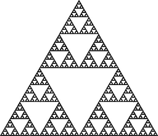
Higher frequency geodesics allow a large dome to be made from a relatively small unit shape.

Each time the size of a dome (radius) is doubled, the surface area is increased by a factor of 4.  This means that a dome twice as big will need 4 times as many blocks.  This reflects Galileo’s Square Cube Law.  Thus doubling the size of a dome uses 4 times as many bricks (surface area is squared) and increases the volume by a factor of 8 (the volume is cubed).  Using 4 times as many bricks creates 8 times as much volume; this is very efficient.

There are some difficulties with higher frequency geodesics.  This is due to the difference between chord length and arc length.  Arc length (S, below) refers to the measurement of the curved surface of a sphere.  Chord length (l, below) refers to the straight line distance between two points on the surface of a sphere.  Arc length is longer than chord length as measured between two points on a sphere.  If a triangle projected onto a spherical surface is broken down into smaller and smaller triangles, then a number of different sized triangles will result.  They are not all the same; there is a maddeningly large number of different dimensions for various triangles.  Historically this has been a challenge for higher order geodesics, often resulting in weakened, leaky or poorly assembled domes. 

Mortar (or gaskets) fixes this problem easily.  The differences in size are accounted for by using more or less mortar (or gasket) between block.  It is a simple matter of aligning block within their geodesic pattern.

Higher frequency domes result in a change in proportions of block.  Because the block are assembling into a larger structure, the wall also gets thicker.  This occurs proportionally: if a structure is twice as big, its walls will be twice as thick.  The result is that unit triangular shapes look less like a thin plate or shell, and more like a thick block.  The thickness is around equal to edge length.  Higher frequency blocks are more “blocky.”  This is advantageous for ceramics or concrete to bear their compressive load.  A block bears compressive load better than a thin plate.

Friday, February 17, 2012

Tension cables in a masonry dome or sphere

The interlocking triangular block which I’ve developed and refer to as a dimp (dual inverse mirror plane) has a symmetry which allows a clear line-of-sight path along the center of each interlocking abutting edge of the block, as shown below.


This means that cable, or wire, or rope, or any appropriate tensile element can be incorporated into an assembled structure.  These cables can be placed on each of the three sides of a given masonry unit and woven together (I ask the reader to forgive my sloppy lines!).


A number of different types of regular polyhedra can be assembled from these triangular interlocking blocks.  These configurations can be used as templates for making spheres, or domes, or parts of domes.  The polyhedra which can be assembled from the hex and pent blocks include icosahedrons, dodecahedrons, icosidodecahedrons, truncated icosahedrons, and snub dodecahedron, among others.
Icosahedron

Dodecahedron

Icosidodecahedron

Truncated Icosahedron

Snub Dodecahedron

 In addition to the different polyhedral arrangements to choose from, different frequencies of these structures can be used to make larger or smaller domes or spheres.  Many different sizes of structures can be made from just a couple of unit shape triangular blocks.

As a given polyhedral dome is built, the first triangular blocks are laid on the starter course.  The starter course is a circular ring.  In between block anchors are cast in the concrete foundation, to which cables are attached.  These cables are placed in the abutting edge of the interlocking face and woven into the structure as it is assembled.  Shown below is a complete sphere being made, with a few of the cable loops pictured (I didn’t draw them all, it would be too sloppy).

Upon completion a sphere or dome has an interconnecting tensile web of great circle arc cables which hold the structure together.  Springs may be incorporated into the cable system to allow movement while also providing a restoring force, which will respond to any deformation by returning the structure to its original round shape.  The drawing below shows just some of the great circle arcs described by weaving cable elements into the abutting edges of blocks.

This tensile configuration system is applicable in cases where extreme loading conditions are expected.  This includes seismic activity, hurricanes, tornadoes, blast resistant structures, hardened structures, etc.

The combination of a mortarless gasket system (as described in my previous entry)  together with a woven tensile cable system creates an efficient, inexpensive, easy to assemble, high performance masonry construction method.

Thursday, March 25, 2010

When Fuller means Less: the weight is over.

I wanted to design a masonry unit (block or brick) which could assemble into an entire structure, including a roof. A sphere seemed like an obvious solution, part of a sphere could be used as a dome.

Work by others such as R. Buckminster Fuller and Barnes Wallis had helped to pave the way. “Bucky” was an odd individual who had some real insight and developed some interesting ideas. He applied himself to doing the most with the least: to enclose the greatest possible volume with the least possible amount of material. This eventually led to what he called a “geodesic.” This sort of geometry has been known since the ancient greeks. I find the Roman Dodecahedron pretty fascinating, their use is still a mystery.

Bucky Fuller used the weight of a structure as a criterion for evaluation. To his way of thinking, if a structure weighed “too much” it was no good. This somewhat arbitrary criterion excluded using inherently heavy masonry as a construction material. For Bucky, structures should be made using the mass-producable methods developed by the US during the war effort of the second world war. Houses should be made of materials like aluminum, mass produced in factories, and we should be able to drop them on site with helicopters. Airstream styling for a brave new world. Look at his ‘dymaxion’ car and house, you get the feel for it.

It turns out that the ‘geodesic’ template lends itself very well to masonry construction. I worked on the specific case of a truncated icosahedron. This is the geometry of a common soccer ball (football for non-Americans) where the black patches are pentagons and the white patches are hexagons. By subdividing these hexagons and pentagons into their respective constituent triangles, we begin to get close to manageable unit shapes.


To make a larger structure, a given unit triangle is simply subdivided into four smaller triangles. By doing this, the unit shape for a large structure can be kept small and manageable for construction purposes.

In considering assembly, I thought it would be advantageous if the blocks could interconnect, or lock together by some sort of retaining system. At first I had a simple hole located on the side of each block, into which a pin could be inserted, connecting two adjacent blocks.


In order to economically mass-produce these unit shapes, they would have to release from a two-piece mold (the sort used by the block industry) without any draft, or undercut, or negative angle. A simple hole to connect blocks -like I had first thought of- creates an undercut. These holes would have to be drilled after the block was made. This was expensive, time-consuming and impractical.
Another obstacle to the idea of interconnecting blocks was that they had to assemble without any undercut. An interlocking feature –by definition, almost- creates an undercut, or draft, or negative angle. An interlock can prevent the blocks from being assembled. How could this be done? That’s for tomorrow.