Showing posts with label architecture. Show all posts

Wednesday, May 29, 2024

Stronger support for ocean front homes and buildings

Houses and buildings located along coastal areas are often susceptible to storm surges of ocean water, especially during hurricanes and extreme weather events. The damage done by this violent weather can be exacerbated by high tides.

These buildings are typically placed atop wooden posts and pilings. This configuration allows a storm surge to pass under the building, so that the building itself is not struck by the full force of a storm surge.  The forces of wind, water and wave are unrelenting for a building located along coastal plains, with a close proximity to the ocean. They are constantly under a barrage or attack by the forces of nature.


As Sea Level Rise (SLR) increases, the effects of wind water and wave are more pronounced on waterfront properties. Failure of the support systems currently used to keep these buildings above the plain of storm surge have become more common. It is expected that this situation will become more widespread and increasingly worse as SLR continues. Recently, failure of these support structures has taken place, especially on the Outer Banks of North Carolina. An article in today's USA Today (May 29, 2024) describes some of this damage.


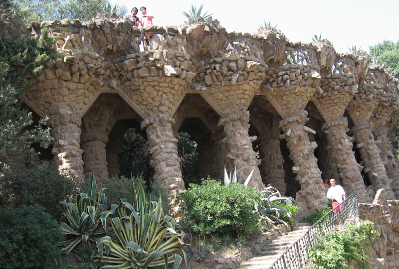
There is a better way to keep a building located in a coastal plain elevated, other than the old, vulnerable method of using wooden posts. High-strength masonry arches, made with an appropriate concrete mix, and reinforced with basaltic FRP (Fiber Reinforced Polymer) rebar provide a very stable configuration. The high strength of concrete exceeds the strength of wood. The proper concrete mix, suitable for marine environments, can last much longer than a piece of wood. The arch configuration of this type of support structure is better able to withstand the lateral forces which are created by waves, wind and water; much stronger and more robust than vertically placed wooden posts.

This method can be rapidly assembled (done in just a few days), it is cost competitive with wooden posts, and it creates a visually striking pedestal for the building. The arches also provide easy access for parking, so the area underneath the building can be readily used.  Any number of platforms can be placed on top of the arch support structure, including reinforced flat concrete slabs, bubble decks, post-tensioned slabs, and so on.

Last summer, we made a concrete ping pong table (table tennis) out of concrete. The legs for the table were made as arches. using basaltic FRP rebar, cast within the concrete forms. This served as a scale model for a structure which could be used to support a building in a coastal plain, subject to storm surges, wave, wind and water. One can imagine this configuration made around 10 times larger; it would provide the perfect platform for building a house in a coastal flood plain, with parking underneath. 


The scalability of these designs is easy to grasp, if one looks at some of the larger arches made from our "Arch" block, which is assembled with 3 pieces of basaltic FRP rebar, as shown below (this shows a 30 ft. span). This configuration is very strong.  The straight sections, or legs, as shown on the corners of the ping pong table can be made from regular CMUs, where the hollow cores are reinforced with grouted FRP rebar. 


This method will allow houses to be built on very strong, affordable, long-lasting, elegant support systems which will allow them to survive further into the future in coastal areas prone to storm surges which are vulnerable to SLR. This will make coastal homes more resilient.


Monday, March 21, 2022

Masonry acoustics, part deux

 I recently finished the second coat of paint on the living room of a building I'm currently completing. Since it is clean and empty, I thought this might be a good time to briefly discuss the room's acoustics.

My dear father left me a pair of Klipschorn speakers, something of a 'classic' pair of loudspeakers, designed and made by Paul Klipsch.  These are a pair of vintage speakers, renowned for their efficiency and warm sound.


Knowing that I wanted to place these speakers in this room, I consulted the Klipsch website to find out what the optimal design and proportions of the room should be. "Klipschorn speakers typically perform best when positioned in the corners on the long wall of a rectangular room. If the room is very narrow and long with corners farther apart than 18 to 20 feet, the stereo image may not be optimal. A room with a length to width ratio of 1.00 to .618 is preferred."  The same ratio is applied to the height of the wall, so that the ratio of the width of the room to its height is 1.00 to .618. These ratios resulted in the room having the dimensions of 30 ft. 8 in. long, by 19 ft. wide, by 11 ft. 8 in. tall.  The arched ceiling goes to a top center height of 16 ft.

The ratio of 1.00 to .618 may sound familiar to any mathematically inclined people.  This is the ratio provided by the Fibonacci sequence.  These ratios are ideally reflected in al three axes: x,y and z.  Thus the proportions of the room are those of a 'golden cube.'  These same ratios are found in the Greek Parthenon.  It is both visually appealing and acoustically beneficial.  Some say that these ratios help prevent constructive or destructive interference of certain frequencies; this idea seems to be disputed by others.


The only other suggestion offered by Klipsch is to include an arched ceiling, for more resonance and a fuller sound.  This room has an arched roof, it's the focus of my work.

The stereo sounds great, it really rocks out: whether it's Beethoven or Jimi Hendrix.

Friday, January 21, 2022

Where is the most stress?

In designing and assembling a masonry building, the engineering work can provide helpful insight which is simple and powerful.  

For example, if we consider the masonry building I'm currently completing, it's insightful to ask: where is the highest stress in the building? Where is the highest compressive force, squeezing together?  Where is the highest tensile force, pulling apart?

The engineering for this building was done by Cheng-Ning Jong, PE.  He has some familiarity with my company's masonry system, since he helped compose, file and prosecute all of our patents.  We've worked together for several years and have a good rapport, a comfortable back-and-forth as we discuss, develop and fully articulate ideas.  

Mr. Jong's most critical role, in my opinion, is the detailing of the reinforcement and the size of the concrete footer from which the stem wall is laid.  A 'footer' is the base of the building, typically located in an excavated trench.  Here's a picture of the footer, with the first few block being arranged for the stem wall:


A stem wall is the bottom section of all the vertical walls buried below the ground, sitting on the footer.  Here is a completed stem wall for a room:

This building has arched masonry roofs, domes, half-domes, flying buttresses, arches meeting at intersections; there is a lot of structural configuration, rebar, weight, stress and so on within the building structure. Here are some architectural drawings, showing some of this detail.  Our architect for this building was Robert Ferry, AIA, RDP.


So if we consider this entire structure, where is the most stress?  Where is the highest compression?  Where is the highest tension?

The highest compression occurs at the bottom of the stem wall, where the stem wall meets the footer, on the outside of the building.  Why?  The entire weight of the building sits on this point.  In addition, the vertical wall acts as a giant lever, translating any thrusting force from the masonry roof and increasing this force by the length of the lever, or wall height to this location. This location, at the corner of the stem wall and the footer, wants to act as a hinge on which the lever of the vertical wall acts.  The highest tension occurs at the bottom of the stem wall, where the stem wall meets the footer, on the inside of the building.  The same lever action of the wall wants to pull up from the hinging on the outside, a mere 8 inches away: the wall thickness.


It's useful to note these areas of high stress.  It makes one pay closer attention to the detailing of rebar, rebar placement, connections, centering, etc., when you are consciously aware that the building you're making will have these high stress locations.  Build accordingly, get it right.


Saturday, July 10, 2010

Antoni Gaudi

“Antoni Plàcid Guillem Gaudí i Cornet” is the Catalan pronunciation of the full name of the artist and architect known to us as Antoni Gaudi (1852-1926). Gaudi is a noteworthy modernist and unique visionary who worked largely on designs gleaned from observation of nature.


His work often used parabolic, hyperbolic and catenary arches; using steel reinforced concrete.

Gaudi used masonry and tile work with an incredible facility of complexity which produced effects almost hallucinatory. He brought life to masonry.

Gaudi was deeply religious; his great unfinished work is the “Sagrada Familia” which is scheduled to open in 2026, the 100th anniversary of his death. The church is to be consecrated by Pope Benedict XVI on November 7, 2010.

Here is Gaudi speaking of Gothic:

"Gothic art is imperfect, it means to solve; it is the style of the compass, the formula of industrial repetition. Its stability is based on the permanent propping of abutments: it is a defective body that holds with support... gothic works produce maximum emotion when they are mutilated, covered with ivy and illuminated by the moon."


An interesting footnote: during the Spanish Civil War, many luminaries of the 1930’s became aware of Gaudi's work; including George Orwell. Gaudi and Orwell are two heroes of mine (one usually wants their friends to get along) but Orwell hated Gaudi’s work. C’mon George, lighten up.

Monday, June 14, 2010

Architectural Jihad!

The block system I’ve been describing on this blog is likely to gain real acceptance as an architectural alternative to conventional construction in other areas of the world, notably the Middle East and Far East.

A dome has become an unusual construction design in the West over the past several centuries. In America today, the dominant balloon frame construction method results in the square and rectangular configurations, like so many cookie-cutter “Monopoly houses” which dominate the American landscape.

In the East, by contrast, a dome is much more culturally acceptable. This is due largely to the beautiful mosque designs which characterize this part of the world. The mosque is often the cultural and social center of a city; thus a dome design is viewed upon much more favorably.

Already, much interest has been expressed by large construction firms from the East in this system. Concrete International, a trade magazine published by the American Concrete Institute, ran a short story on my block system, and numerous inquiries from large construction firms across the Middle East and Far East made formal inquiries into this masonry system.

In my last blog entry, I discussed using this masonry system for water storage, septic systems, and desalination applications. A global effort to launch this system for these utilitarian applications would also make it available for architectural applications, whose use as an architectural dome is more culturally accepted than in the West.

This use of masonry to build architectural domes also provides buildings which will withstand monsoons, typhoons, fire, termites, and does not require wood for construction. It seems like a good fit culturally, socially, economically and from an engineering standpoint; providing buildings with a long and useful life cycle. Finally, this is a sustainable use of resources which will help preserve valuable wood, and creates an energy efficient structure.

A modest architectural revolution seems in the offing, whose acceptance in other parts of the world could play a significant role in the future of building.

Friday, May 7, 2010

Glass Block: a new design

The block system described in this blog readily lends itself to being made with glass. Today we’ll take a look at glass block, and how it would be suitable for this masonry system.


Glass block has become a fairly widespread construction material. As with concrete block, glass block are currently limited to square and rectangular blocks. This limits the architectural applications of glass block to straight vertical walls and square corners. Some block designs include curved corners, but currently no glass block can be used for spherical or dome sections, as I’m proposing here. It’s interesting to me how regular glass block today says “1980’s” and is not considered current, or ‘in vogue.’

Glass block is manufactured by first forming two pieces of glass, and then joining them while the glass is still warm enough to be moveable (at around 800 degrees F). The two pieces are pinched together in a two-piece mold and allowed to anneal, or cool slowly to reduce thermal stresses and obtain a thermally stable object. If the hot glass is not properly annealed, it will crack some time after it is removed from heat.

Hollow glass block creates a decent thermal insulator, and saves heating and cooling requirements for a given building.

Interestingly (perhaps counter-intuitively) glass has a high strength: higher than concrete in some cases. The theoretical strength of glass is very high, and is only reduced by small surface flaws which create starting points for cracks to begin and significantly lowers the actual strength of glass.

Glass can be greatly strengthened by using a technique called ‘ion substitution.’ Glass typically is made with a flux agent, which lowers the melting temperature of the glass. Sodium is a common flux, and is typically found in silicate glasses. If a sodium silicate glass is immersed in a heated bath, comprised of (for example) potassium compounds (e.g. KOH), then the potassium will migrate into the glass, and replace sodium. Potassium is larger (ionic radius) than sodium, so it ‘stuffs’ the glass and creates compression in the glass; resulting in a much stronger glass. This method could be used to create very high strength architectural glass block.

The block system I’ve been describing in this blog is made on a two-piece mold, without any undercut. This is what is required to make hollow glass block. The block system I’ve been describing is appropriate and suitable for producing hollow architectural block.

The glass block produced from this masonry system can be used to assemble spheres, domes, arches, straight walls, and various combinations of these architectural elements. These blocks will all interlock, they are disposed to conjugate shearing without breaking, they can use a series of tensile elements (e.g., steel cable, Kevlar, etc.) to provide a much higher strength to the entire structure.

Glass block can also be used together with concrete block. This is important because glass block is more expensive than concrete, so it can be used as a highlight feature, and bring some dramatic lighting elements to an overall structure. Glass block can also be used to build a small dome, which could be incorporated as a cupola, or an architectural feature within a building. Imagine a glass dome at the top of a foyer or entryway into a building or house.

The symmetry and hexagonal elements inherent to this masonry system produces a ‘snowflake’ effect, where the architecture has a close resemblance to the beauty and symmetry found in snowflakes.

Sunday, April 18, 2010

Architectural Applications

Architectural applications for this masonry system create interesting opportunities in terms of design and arrangement. This system provides a number of benefits that make a compelling case for its use.  Below is a view looking up at a ceiling, into the cupola.


This system is relatively inexpensive. The cost of these blocks is comparable to the cost of regular concrete block, around $2-3 per block, depending on where it is purchased. For a second order dome, the cost of the dome is under $1,000. This structure is highly efficient to heat and cool, very strong, virtually maintenance free, and can be expected to last for centuries. These structures are fire proof, termite proof and will not rot.

No trees are required for this masonry system, wood can be used as needed.  Recycled material is commonly used in manufactured block. Taken together with the very long life cycle of this structure, it is a green construction method.


These buildings have a very high strength, and are appropriate for areas prone to tornados, hurricanes, and violent weather. For tornado and hurricane prone areas, a secure “safe room” can be inexpensively provided with this system.

The extensive design flexibility inherent to this masonry system provides architects with a number of interesting ways to arrange various elements of a building. This system is appropriate for both commercial and residential applications. It is also suitable for institutional buildings, including schools, municipal buildings, etc.


I’ll be posting pictures of these blocks being used later in this blog, showing different methods, stages and uses.

Meanwhile I’ll continue with describing the various applications which I listed in my last post.