Friday, January 21, 2022

Where is the most stress?

In designing and assembling a masonry building, the engineering work can provide helpful insight which is simple and powerful.  

For example, if we consider the masonry building I'm currently completing, it's insightful to ask: where is the highest stress in the building? Where is the highest compressive force, squeezing together?  Where is the highest tensile force, pulling apart?

The engineering for this building was done by Cheng-Ning Jong, PE.  He has some familiarity with my company's masonry system, since he helped compose, file and prosecute all of our patents.  We've worked together for several years and have a good rapport, a comfortable back-and-forth as we discuss, develop and fully articulate ideas.  

Mr. Jong's most critical role, in my opinion, is the detailing of the reinforcement and the size of the concrete footer from which the stem wall is laid.  A 'footer' is the base of the building, typically located in an excavated trench.  Here's a picture of the footer, with the first few block being arranged for the stem wall:


A stem wall is the bottom section of all the vertical walls buried below the ground, sitting on the footer.  Here is a completed stem wall for a room:

This building has arched masonry roofs, domes, half-domes, flying buttresses, arches meeting at intersections; there is a lot of structural configuration, rebar, weight, stress and so on within the building structure. Here are some architectural drawings, showing some of this detail.  Our architect for this building was Robert Ferry, AIA, RDP.


So if we consider this entire structure, where is the most stress?  Where is the highest compression?  Where is the highest tension?

The highest compression occurs at the bottom of the stem wall, where the stem wall meets the footer, on the outside of the building.  Why?  The entire weight of the building sits on this point.  In addition, the vertical wall acts as a giant lever, translating any thrusting force from the masonry roof and increasing this force by the length of the lever, or wall height to this location. This location, at the corner of the stem wall and the footer, wants to act as a hinge on which the lever of the vertical wall acts.  The highest tension occurs at the bottom of the stem wall, where the stem wall meets the footer, on the inside of the building.  The same lever action of the wall wants to pull up from the hinging on the outside, a mere 8 inches away: the wall thickness.


It's useful to note these areas of high stress.  It makes one pay closer attention to the detailing of rebar, rebar placement, connections, centering, etc., when you are consciously aware that the building you're making will have these high stress locations.  Build accordingly, get it right.


Wednesday, January 19, 2022

Finishing a masonry closet

I've just finished a closet in a masonry building I'm making. A closet allows me to try certain steps, before committing such steps to the entire building.  

How will the drywall work? Test it in the closet.

How will the paint look? Try the closet.  


It's a pretty cool closet. A right triangle floor, with a half-dome ceiling.


Monday, January 17, 2022

Snow covered masonry buildings

 I awoke to a beautiful 15 inches of fresh powder.  I took a few pictures of these masonry buildings covered in snow.  The domes, arches, catenary forms: all seem to create interesting topological snow surfaces.   

Sometimes people will ask about how appropriate a masonry roof is for big snow loads?  They only get stronger with more weight, and the snow also helps insulate even more.  These buildings can handle extreme snow loads.

View out my bedroom window.


Saturday, October 30, 2021

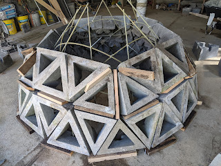
Assembling a self-supporting masonry dome

Here are the basic steps to assemble a first frequency truncated icosahedron from 'pent' and 'hex' concrete block, as provided by Spherical Block. Trace out a circle of radius 3 ft. 1 inch.  Arrange the block in a five-fold, or pentagonal pattern, one pent, two hex, [repeat 5X]. Arrange all blocks with tips pointing up. 


Next, place blocks with tips pointing down, two pent, one hex, [repeat 5X]. FRP, Fiber Reinforced Plastic rebar is used here, #3, or 3/8 inch diameter. Rebar is 8 ft. 10 inches, and goes from center hex block and is easily bent  past two pent and into the next center hex, as shown. 


Additional rebar is provided horizontally, as shown. Length is 41 inches. Rebar is secured with zip ties, to help align the structure.

Hex block are placed, tip pointing up, as shown.  

Because this is a first frequency structure, and is made from block designed for a second frequency structure, wooden shims were used during this dry-stack assembly.  This gave the blocks the increased 'wedge' required for first order arrangement. When using mortar, the mortar will be tapered for a first frequency dome; thicker outside.


Additional rebar are placed vertically, as shown, attached with zip ties. These are also 41 inches long. Additional pent blocks are placed, as shown


Two more hex blocks are placed, tips down, as shown.


An additional course of hex block are added, as shown.


Finally, 5 pent blocks are added to the top and final course. All of these block edges would be in close alignment if this were mortared together. Assembly occurs without any additional support scaffolding or centering. This first frequency dome has an outer diameter of around 8 ft.


The first frequency test was easily disassembled.  A second frequency dome is now being assembled.

Here are the same basic steps, except that the radius is doubled and 4 times as many block are used. This second frequency dome has an outer diameter of around 16 feet. 2 pent, 4 hex, 5X, etc., tips up.


And so on. It is all self-supporting as it is assembled. Larger domes of higher frequencies can also be made, all from the same block.

Friday, September 3, 2021

Floor, walls and bond beam

 This material is based upon work supported by the National Science Foundation under Grant No. 1660075 ("Topological interlocking manufactured concrete block").  Any opinions, findings, and conclusions or recommendations expressed in this material are those of the author, and do not necessarily reflect the views of the National Science Foundation.

The previous post showed how we excavated, poured the footer and built the stem wall.  Following this, the vertical walls were assembled and the floor was installed. The floors are made to accommodate a radiant heating system. First a rigid foam is laid down, on the level compacted ground floor; then "Pex" TM pipe was installed.  


Concrete was then poured on top of the foam and pex, and screeded level, then the floor surface was floated. 


The walls were built up to header height, then a temporary scaffolding was built for roof assembly.  All exterior doorways had a masonry arch built over them, using wooden forms. The arches are fast and easy to assemble, they are also inexpensive.


After all the vertical walls were assembled, forms were built at the top of these walls; rebar was placed in this cavity as per the PE specification, and the form was poured with concrete to create a reinforced bond beam. 


With the bond beam made, roof construction was about to begin.  That's what I'll describe and show next..