Saturday, July 24, 2010

Phi Fi Fo Fum

In my last entry I asked: how do the great pyramids of Giza have the same precise angle of slope as the location of a haunch in a barrel vault? This is an interesting question which delves into geometry and the Golden Mean, or Golden ratio.


As described in Wikipedia: “in mathematics and the arts, two quantities are in the golden ratio if the ratio of the sum of the quantities to the larger quantity is equal to (=) the ratio of the larger quantity to the smaller one. The golden ratio is an irrational mathematical constant, approximately 1.6180339887. Other names frequently used for the golden ratio are the golden section (Latin: sectio aurea) and golden mean. Other terms encountered include extreme and mean ratio, medial section, divine proportion, divine section (Latin: sectio divina), golden proportion, golden cut, golden number, and mean of Phidias. The golden ratio is often denoted by the Greek letter phi, usually lower case (φ)” [pronounced "fee"].

The pyramids of Giza used the Golden Mean in their basic design and construction. If the edge of the base of the pyramid is taken as 2, then the height of the pyramid is the square root of phi, and the hypotenuse of this right triangle is phi.

How does the golden mean relate to a sphere? It relates to the sphere through a polyhedron known as an icosahedron, which can be traced onto a sphere. Here is an icosahedron:

These images shows three rectangular planes at right angles to each other (x,y,z) which each have the edge length proportions of the golden ratio (1:1.618...).  If the corners of these three rectangles are connected, they describe an icosahedron on a sphere.  This is a sculpture I made from clay.

Here are the three phi rectangles assembled:


Here are the rectangles being placed in the sphere:

Here is the assembled structure, showing the relationship between phi and a sphere, through the icosahedron:


So the why does the haunch of a Roman Arch (circular vault) occur at an angle which is exactly the same as the slope of a pyramid? This remains an interesting question, especially since most Egyptian ‘arches’ were not arches at all, but post and lintels. It is true that Egyptians built with arches, but they never developed the masonry arch as did the Romans.

This remains a mystery to me. If anyone has any idea, please share and let me know. It seems too precise of a coincidence that both the haunch angle in a circular arch and the phi-based geometry of the great pyramids at Giza should both manifest the specific angle of 51 degrees, 51 minutes. Furthermore, the haunch is a result of gravity acting on a body; whereas geometric constructions relying on the golden ratio appear to be independent of any force, such as gravity. This is a very curious coincidence.

Incredible Insight, felt in your bones

The master masons of antiquity are often described as having an intuitive sense of stresses, load bearing and stress analysis. It is sometimes said that they “felt it in their bones,” and were able to translate this intuitive sense into an articulated design for masonry.


The thigh bone figures prominently in this schema. The ancient symbol of freemasonry uses skull and crossbones: the crossbones include the femur, or thighbone. This symbol is also known by the Greek letters Chi and Rho, which are taken to represent Christ. This is all fundamental, significant and important symbolism. The Chi may be taken as the thighbones, and the Rho may be taken as the skull.

In a masonry barrel vault (or semi-circular) arch, the most critical section is known as the “haunch.” A haunch is defined as the upper thigh in humans. This corresponds to the femur.  Here is a wonderful discussion of haunches from 1838.

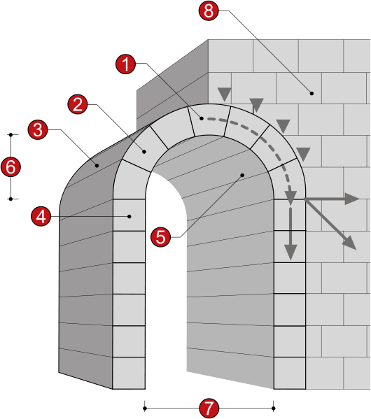
In a semicircular arch –whether a cylindrical arch or a dome- there are compressive forces due to gravity, pointing down; and there are thrusting forces, pointing out. As we come down from the top or crest of the arch, the compressive forces (meridional forces) change to tension forces (hoop forces) at a specific location in the arch, known as the haunch. This haunch occurs at 51degrees 51’ in the arch.

This location in the arch (look at this link) is where the catenary thrust lines come closest to the inside surface of the arch (known as the intrados). It is the location where exterior loading is most necessary to strengthen the arch. This is done by moving the thrust force lines closer to the center of the wall, as discussed earlier.

If we look at the design I use to join arches at right angles to each other, which I discussed earlier in this blog, these arches abut each other at the precise location of the haunch. That is, arches serve to reinforce and support one another by meeting precisely at 51degrees 51’, at the haunch. It seems there is something fundamental occurring here.  I came across this independently, this is a drawing from one of my patents.

It further seems that this critical angle of the haunch within an arch has been known since very early in masonry. The specific angle of the haunch –as occurring at 51degrees51’- appears to have been known by the ancient masons of Egypt. The great pyramids were developed over time and across generations. They perhaps reached their highest state in the pyramids of Giza.

The slope, or angle of the ancient pyramids at Giza is specifically 51degrees51’. I find this amazing.

How much did the masons of antiquity know? How did they arrive at their knowledge? Was it all gained empirically, or theoretically, or some combination of the two? Did they feel it in their bones?

We have already seen how these ancient masons developed simple geometric rules which refuted theories proposed and propounded by Galileo. We will continue to look at some of the knowledge developed by early masons in the context of current knowledge and engineering analysis. This is a fascinating subject which merits further investigation.

Friday, July 23, 2010

Can a mason build a submarine?

Can a mason build a submarine? It sounds kind of silly.


I have made several references in this blog to high strength underwater spheres made of concrete. A great deal of research has actually been conducted on this topic, mostly by the U.S. Navy and also by oil companies involved in deepwater drilling.

Mr. Wellmer, of http://www.boatdesign.net/, has collected much information on concrete submarines and has built several concrete submarines. He is an enthusiast of concrete submarines (personally I like Led Zeppelins).

As Mr. Wellmer states on his website, “…you get a giant hull that is surprisingly pressure resistant, comfortable, and maintenance free, at moderate cost…a concrete hull will be fine with the same level of maintenance that have submarine tunnels, oil rigs, bridge foundations, to keep it barnacle free you have to scrap them off. What is different to a wood, or steel hull is that the material needs no attention at all. No sandblasting, painting, drydock. - once in water it can stay there for several decades. This is a major cost saver…”

And here he discusses the benefits of concrete versus steel:
“Of course you can drill concrete - easier than steel.

Reliable thru hulls - never had a problem ...

Never had a drama with a hatch.

Steel and concrete have very similar expansion rates this makes steelbars in concrete as a compound material possible.

I am not aware that submarine concrete projects like eurotunnel, Troll A, etc use concrete for lame ass money saving - very particular point of view.

Structural concrete engineering has 2000 years of tradition going back to ancient rome ...

The blimp shape is because it is the BEST shape and you can form concrete to ANY shape and thickness which is not the case in steel.

No rocking on anchor place - not my submarine yachts.

Concrete is the most quality controlled and controllable material in the engineering world.

Yes you trust concrete every time you enter a building with thousands of tons of pressure in the columns and changing wind loads all the time.

On of the BIG advantage of concrete is that it gives clear visible warning before weakening by rust brings up failure - any civil engineer can orient you on that.”

Then several papers, mostly by the Navy, are cited, which provide more insight into concrete submarines and concrete spheres. This first one describes how a concrete sphere for underwater use is better without any steel reinforcement:
-------------------------------------
Title : Behavior of Steel Bar Reinforced Concrete Spheres under Hydrostatic Loading.


Descriptive Note : Technical note Jun 71-Oct 73,


Corporate Author : CIVIL ENGINEERING LAB (NAVY) PORT HUENEME CALIF


Personal Author(s) : Albertsen,N. D.


Report Date : APR 1975


Pagination or Media Count : 27


Abstract : Four reinforced and two unreinforced concrete spheres of 32.00-inch outside diameter (OD) and 2.71-inch wall thickness (t) were tested under hydrostatic loading to determine the effect of embedded steel reinforcement on structural behavior. Test results show that the reinforced spheres (0.44 or 1.10% steel by area) failed by implosion at values for the ratio of implosion pressure to concrete strength that were on the average 5% lower than for the unreinforced spheres of the same size. In addition, the reinforced spheres developed cracks in-the-plane-of-the-wall at the inner surface of the reinforcement cage prior to implosion. Implosion results for the unreinforced spheres are 10% lower than predicted by an empirical equation developed from previous tests of unreinforced 16-inch OD spheres. These results provide initial insight into the behavior of hydrostatically loaded steel bar reinforced concrete spheres and indicate that additional test data is required before definitive design guides can be developed.
-----------------------------------------------------
Here’s a paper discussing at what water depth concrete spheres implode (this is from 1968, a little dated):
-----------------------------------------------------
BEHAVIOR OF SPHERICAL CONCRETE HULLS UNDER HYDROSTATIC LOADING-PART III.


Relationship Between thickness-To-Diameter Ratio and Critical Pressures, Strains, and Water permeation Rates, Technical Report R588, Naval Civil Engineering laboratory, Port Hueneme, CA, by J.D. Stachiw and K. Mack, June 1968, 36 pages.


Sixteen hollow concrete spheres of 16-inch outside diameter were subjected to external hydrostatic pressure to investigate the relationship between the sphere's shell thickness and (1) its critical pressure, (2) permeability, and (3) strain magnitude. The shell thickness of the spheres varied from 1 inch to 4 inches in 1-inch steps. All spheres were cast from the same concrete mix, cured under identical temperature and moisture conditions, and tested in the same manner. The strength of concrete in the spheres at the time of testing, as established by uniaxial compression tests on 3 x 6-inch cylinders, was in the 9,000-to-11,000-psi range. The critical pressure of waterproofed hollow concrete spheres was found to be approximately a linear function of the sphere's thickness; the spheres imploded at pressures from 3,240 to 13,900 psi, depending on their thickness. Concrete spheres permeated by seawater failed at hydrostatic pressures 30% to 15% lower than identical waterproofed spheres. In all cases the stress in the spheres at the time of implosion was considerably higher than in concrete test cylinders prepared of the same mix and of the same curing history subjected to uniaxial compression. The resistance of concrete to permeation by seawater into the interior of nonwater proofed spheres at 2,000-psi hydrostatic pressure was found to be an exponential function of shell thickness. The rate of flow into the sphere's interior ranged from 6.1 to 0.197 ml/day/ ft2 of exterior surface, depending on the thickness of shell.
-----------------------------------------------
Yet another paper on long term, deep depth testing of concrete spheres:

Title : Long-Term, Deep Ocean Test of Concrete Spherical Structures - Results after 13 Years.


Descriptive Note : Technical rept. Mar 78-Nov 84,


Corporate Author : NAVAL CIVIL ENGINEERING LAB PORT HUENEME CA


Personal Author(s) : Rail,R. D. ; Wendt,R. L.


Report Date : JUL 1985


Pagination or Media Count : 70


Abstract : In 1971, a long-term, deep-ocean test was started on 18 pressure-resistant, hollow concrete spheres, 66 inches in outside diameter by 4.12 inches in wall thickness. The spheres were placed in the ocean near the seafloor at depths from 1,840 to 5,075 feet. Over a 13 year period, annual inspections of the spheres using submersibles have provided data on time-dependent failure and permeability. After 5.3 years of exposure, three spheres were retrieved from the ocean for laboratory testing, and after 10.5 years two more spheres were retrieved and tested. This report is the third report in a series describing and summarizing the findings from the ocean and laboratory tests. Data on concrete compressive strength gain, short-term implosion strength of the retrieved spheres, and permeability and durability of the concrete were obtained. The data have shown that concrete exhibits good behavior for ocean applications. High quality, well-cured concrete can be expected to gain and maintain strength when submerged in seawater under high pressure. Concrete is a durable material in the deep ocean; neither deterioration of the concrete matrix nor corrosion of reinforcing steel are problems, even though the concrete becomes saturated with seawater. Uncoated concrete has a very low rate of premeation of seawater through the concrete and even this small flow can be prevented by a waterproofing coating. (Author)


Descriptors : *CONCRETE, *STRENGTH(MECHANICS), *UNDERWATER STRUCTURES, *DEEP OCEANS, THICKNESS, PERMEABILITY, LABORATORY TESTS, CORROSION, TIME DEPENDENCE, FAILURE, HIGH PRESSURE, SPHERES, DEPTH, STEEL, SHORT RANGE(TIME), COATINGS, STRENGTH(GENERAL), GAIN, INSPECTION, WALLS, FLOW, OCEANS, DETERIORATION, SEA WATER, LOW RATE, OCEAN BOTTOM, REINFORCING MATERIALS, COMPRESSIVE PROPERTIES, WATERPROOFING, SUBMERSIBLES, IMPLOSIONS.


Subject Categories : PHYSICAL AND DYNAMIC OCEANOGRAPHY

CERAMICS, REFRACTORIES AND GLASS


Distribution Statement : APPROVED FOR PUBLIC RELEASE

Finally, three more Navy papers discussing concrete spheres at depth:

Corporate Author : CIVIL ENGINEERING LAB (NAVY) PORT HUENEME CA


Personal Author(s) : Haynes,Harvey H. ; Highberg ,Roy S.


Report Date : JAN 1979


Pagination or Media Count : 53


Abstract : In 1971, a long-term, deep-ocean test was started on eighteen concrete spheres, 66 inches (1, 676 mm) in outside diameter by 4,12 inches (105 mm) in wall thickness. The spheres were placed in the ocean at depths from 1,840 to 5,075 feet (560 to 1,547 m). Over a 6.4-year period, yearly inspections of the spheres by submersibles have provided data on time-depedent failure and permeability. After 5.3 years, three of the spheres were retrieved from the ocean for laboratory testing. Data on concrete compressive strength gain, short-term implosion strength of the three retrieved spheres, and permeability and durability of the concrete were obtained. This report summarizes the findings from the laboratory and ocean tests. (Author)


Descriptors : *CONCRETE, *UNDERWATER STRUCTURES, PERMEABILITY, PERFORMANCE(ENGINEERING), LOADS(FORCES), SHELLS(STRUCTURAL FORMS), SPHERES, STRENGTH(MECHANICS), LONG RANGE(TIME), SATURATION, PROTECTIVE COATINGS, WALLS, MARINE ENGINEERING, DEEP OCEANS, COMPRESSIVE PROPERTIES, WATERPROOFING, STRUCTURAL ENGINEERING, SEA TESTING, HYDROSTATIC PRESSURE, IMPLOSIONS.


-----------------


Descriptive Note : Technical rept. Jun 68-Jul 71,


Corporate Author : NAVAL CIVIL ENGINEERING LAB PORT HUENEME CALIF


Personal Author(s) : Haynes,H. H. ; Kahn,L. F.


Report Date : SEP 1972


Pagination or Media Count : 93


Abstract : Fourteen unreinforced concrete and mortar spheres, 66 inches in outside diameter (OD) and 4.125 inches in wall thickness, were subjected to simulated deep-ocean loading conditions. The average short-term implosion pressure for wet-concrete spheres was 2,350 psi and for the dry-concrete spheres was 2,810 psi; the average uniaxial compressive strength of the concrete was respectively 7,810 psi and 9,190 psi. Under long-term loading, the concrete spheres failed by static fatigue where the relation between level of sustained pressure and time to implosion was similar to that known for concrete under uniaxial loading. Wet-concrete spehres under seawater pressure as high as 1.670 psi showed an average D'Arcy's permeability coefficient, K sub c, of 10 to the minus 12 power ft/sec; this K sub c value was also similar to that known for concrete under freqhwater pressure as high as 400 psi. Design guides were developed to predict the short- and long-term implosion pressures and permeability rates of concrete spheres. (Author)


Descriptors : (*UNDERWATER VEHICLES, HYDROSTATICS), (*SHELLS(STRUCTURAL FORMS), *CONCRETE), (*SPHERES, CONCRETE), COMPRESSIVE PROPERTIES, PRESSURIZATION, LOADS(FORCES), DEFORMATION, STRAIN(MECHANICS), RUPTURE, DEEP WATER


Subject Categories : MARINE ENGINEERING

MECHANICS


-------------------------------


A Decade of Ocean Testing of Pressure-Resistant Concrete Structures

Rail, R.

Naval Civil Engineering Laboratory, Port Hueneme, CA, USA;


This paper appears in: OCEANS

Publication Date: Aug 1983

Volume: 15, On page(s): 593- 597

Current Version Published: 2003-01-06

Abstract

By means of long-term deep-ocean exposure and laboratory testing, experimental data have been obtained on compressive strength behavior, permeability, and durability of pressure-resistant concrete structural models (concrete spheres 66-inch O.D. by 4-1/8-inch wall thickness) subjected to continuously sustained hydrostatic pressure loading. After 10-1/2 years of ocean exposure at water depths of 1,840 to 5,075 feet, the major findings include: (a) The implosion (failure) strength and stiffness of the concrete spheres and the uniaxial compressive strength of concrete specimens increased during the first 5-1/2 years exposure in the ocean and remained essentially constant during the next 5 years; (b) There has been no evidence of seawater permeating through the walls into the interior of ocean-exposed spheres externally coated with a waterproofing material; uncoated (bare concrete) spheres have a very low rate of water ingress, i.e., a permeability coefficient of about10^{-14}ft/ sec; and (c) Visual inspection and microstructure examination of retrieved specimens have not revealed any significant deterioration of the concrete matrix; no corrosion was visible on steel reinforcing bars which had as little as one inch clear cover. This program has been a decade-long demonstration of the effective use of concrete in the ocean; it has been shown that concrete is a durable, reliable material for pressure-resistant structures for long-term deep-ocean applications.
-----------------------------------------------
Can a mason build a submarine? Does it still sound so crazy?

Next time we'll look at concrete canoes, and no: I'm not joking.

Thursday, July 22, 2010

Galileo's Thirst for Knowledge: Priceless. Quenched: $470 Billion.

Over the past three entries I wrote about Galileo’s mistaken approach toward analyzing masonry domes and arches, where he invoked his Square Cube Law to wrongfully criticize the work of ancient master masons. One of the insights gained from a proper and correct stress analysis, which involves thrust force lines describing a catenary curve within the thickness of an arch wall, is that extra weight, or loading, applied to the outside of an arch actually makes the arch stronger by keeping the thrust force lines closer to the center of the arch wall.


The implications of this correct structural analysis are far-reaching and insightful, for numerous applications of masonry structures: some of which I have already been discussing in this blog.

If a complete sphere is assembled, and this complete sphere is submerged below water, the water applies a load to the outside of the sphere. Water pushes in on the round sphere fairly equally, all the way around the sphere from all directions. This external loading keeps the thrust line forces equally distributed around the entire sphere, and it keeps these thrust line forces located in the center of the wall thickness, resulting in an optimal loading of compressive forces. Any other shape, whether it is a cube, rectangular, elliptical, etc., will not distribute this external loading in an equal, symmetrical manner as a sphere does.

This attribute of a masonry sphere subject to external compressive forces bearing such loading equally and symmetrically about its surface means that a below ground storage tank, built as a sphere, is an ideal configuration for any below ground tank. If a below ground tank is used to store water, then the weight of the water will apply an interior force, or head pressure, against the inside of the sphere, so that this force weakens the sphere and must be countered by an external force. Given that the density of water is 1.0 grams/cubic cm, and that average soils have a density of around between 2 and 3 g/cc, it is obvious that the external forces of the surrounding soil are 2 or 3 times the internal pressure of the water held in the tank. In other words, there is substantially greater compressive force acting on the outside of the sphere from the surrounding soil than there is acting on the inside of the tank by the water stored there.

These examples further illustrate that a masonry sphere used as either a below-ground water storage tank or as a means of desalination, as discussed here and there in this blog, are ideal solutions to the growing global problem of potable water use, storage and procurement. This water problem can be addressed by the existing manufacturing capability of the concrete block industry, using its existing methods, materials, and infrastructure. This can be done in an economical, sustainable and easily implemented manner.

This represents a huge market, and the proposed technology could be a big part of the answer to a pressing problem which is expected to worsen with climate change and the growing needs of humanity. Currently, the size of the market for potable water is estimated at $470 billion. One in eight people around the globe lack access to fresh water; that’s almost one billion people. The solution described here could help address this problem.

To see a completed prototype for water storage, please look here.

Wednesday, July 21, 2010

Lessons learned from Galileo's mistake

For the past two entries on this blog, I looked at Galileo’s valuable insight known to us today as the Square Cube Law. Galileo made the mistake of applying the Square Cube Law to masonry arches. He said (p.33) “The great Master Builders of the past used proportional design rules, which are essentially incorrect. Using these rules they built masterpieces of architecture and engineering of the past.” But it was Galileo who was essentially incorrect.


As we wrap up our discussion of Galileo’s incorrect application of the Square Cube Law, a few things stand out from the insight gained by a correct analysis of arches, stresses, and load-bearing ability.

First, the important concept of a catenary is made even more emphatic, and trumps the role of the Square Cube Law. As discussed earlier, a catenary comes from the Latin word “catena” which means chain. Architects also use the term “funicular” to describe the catenary curve; from the Latin “funis” meaning rope or cable. When speaking of masonry, “catenary” is actually a more accurate term, because a masonry arch is comprised of voussoirs, or individual masonry blocks, which are analogous to the individual links of a chain; not the smooth continuity of a rope or cable.

In every arch which is built and stays standing, there can be traced a catenary curve within the wall thickness, described by the thrust force lines which represent the force of gravity acting on the voussoirs. If this catenary curve goes outside of the wall thickness, then a hinge is created, the arch will buckle at this hinge, and it will collapse.

As long as the catenary curve fits within the wall thickness, walls can be made thinner and thinner. Furthermore, the addition of loads onto a masonry arch tends to keep the thrust force lines within the wall thickness: so that adding weight can actually strengthen a masonry arch or dome.

This is the essential design analysis for masonry arches and domes. It really has nothing to do with Galileo’s Square Cube Law. Whether by conscious design and intuitive insight, or merely by trial and error, the master masons of antiquity always fit the catenary curve within their wall thickness by using their simple rules of geometric proportion; this is why their structures could be made small or large, and this is why their incredible feats of engineering and art still stand today to inspire us and enrich us.

Tuesday, July 20, 2010

More on Galileo and Master Masons

In my last blog entry, I began a discussion of an article by Santiago Huerta, Galileo was Wrong! the Geometrical Design of Masonry Arches, Nexus Network Journal, Volume 8, No. 2, 2006.  The link to this article is worth taking a look at; Dr. Huerta uses many excellent illustrations to demonstrate his salient points.


Dr. Huerta provides some valuable insight into the engineering analysis of masonry domes and arches. He argues that the proportional design of arches, as used by master masons of antiquity, has provided a tool for arch construction which has proven successful and is more accurate than the approach first described by Galileo in his famous paper “Dialogues Concerning Two New Sciences” of 1638.

If we look at the components that comprise a masonry arch, known as voussoirs, and perform an analysis of their thrusting forces under gravity, the resulting thrust line analysis provides critical insight into the strength of masonry arches. I briefly referred to this method of analysis in an earlier blog entry while discussing Gothic arches, using the illustration below.

The thrust lines may be drawn to represent the gravitational forces acting on the individual voussoirs within the arch. As long as these thrust lines are within the wall thickness of the arch, the structure is stable, and will remain in a static state of equilibrium.

Master masons of antiquity, in using their geometrical approach (as discussed in my last entry) consistently provide a structure wherein the thrust line analysis yields a stable structure in equilibrium. This analysis remains consistent even when the structure is scaled up, or made much larger. This scale ability is in direct contradiction to Galileo’s “Square Cube Law” which states that as scale increases, the design must account for the fact that while cross sectional area of material increases as a squared function, the volume (and hence mass) increases as a cubed function.  This relates directly to the concept of Allometry, or the relationship between size and shape.

This insight –and refutation of Galileo- has some profound implications for analysis and design of masonry arches. Thrust line analysis is different than other methods of stress analysis within a structure. One common method of stress analysis today is Finite Element Analysis, as performed by students who did work on my masonry system and provided their own Finite Element Analysis, as shown here several entries ago. A thrust line analysis is superior to Finite Element Analysis in providing specific tools and insight into masonry arch construction.

In performing a thrust line analysis on a masonry arch, it becomes obvious that if a circular arch (or barrel vault) or hemisphere (or dome) is built, the thrusting forces (pushing out) are greatest toward the bottom of the vault, or dome, or hemisphere. This is accommodated by simply making the wall thicker, so as to keep the thrust lines within the (thicker) wall. Taking this approach a step further, if the arch, or dome, or hemisphere is truncated at the base, or taken as a smaller section which is less than a full hemisphere, then the entire arch wall may be made substantially thinner: because the thrust lines no longer go to the bottom of a full semi-circle (where they splay out) and can be kept within the wall thickness of a thinner wall. The key to performing this arch truncation in a structurally sound manner is to provide a thick abutment at the base of the dome section, so that thrusting forces are resolved here. This insight allows for arches and domes to be made substantially thinner.

The insight of thrust line analysis is ultimately a succinct and quantified summary of the reasons for building arches as catenary arches, as discussed earlier in this blog.


Monday, July 19, 2010

Master Masons: Smarter than Galileo?

I recently read a fascinating article by Santiago Huerta, a Spanish architect whose expertise lies in the structural analysis of arches and domes. (Galileo was Wrong! the Geometrical Design of Masonry Arches, Nexus Network Journal, Volume 8, No. 2, 2006).


Mr. Huerta describes how since antiquity, master masons have always used simple geometric rules involving proportions to design arches. For example, if an arch is a certain length (or span) it must be a certain thickness. It is a proportional design independent of scale. This method was developed before (and independent of) any formal scientific method. This system employed by ancient master masons has proven very effective, as demonstrated by the existence of numerous large masonry structures which have survived over millennia, as discussed several times earlier on this blog.

The proportional approach is a geometric approach: designs are scale able, an arch design which is 10 ft wide and one foot thick can also be made 30 feet wide and 3 feet thick. This approach was used for hundreds (even thousands) of years before it was questioned by Galileo.

In 1638 Galileo attacked this simple approach used by master masons in his work Discorsi e Dimostrazioni Matematiche intorno à due nuove sicenze Attenenti alla Mecanica & i movimenti Locali (Dialogues Concerning Two New Sciences). Here, for the first time, was an articulation of what has come to be known as the Square Cube Law.

Here is Galileo attacking the method of proportions in rumination on his research to his colleague, Giovanni Francesco Sagredo:   “Therefore, Sagredo, you would do well to change the opinion which you, and perhaps also many other students of mechanics, have entertained concerning the ability of machines and structures to resist external disturbances, thinking that when they are built of the same material and maintain the same ratio between parts, they are able equally, or rather proportionally, to resist or yield to such external disturbances and blows. For we can demonstrate by geometry that the large machine is not proportionally stronger that the small. Finally we may say that, for every machine and structure, whether artificial or natural, there is set a necessary limit beyond which neither art nor nature can pass; it is here understood, of course, that the material is the same and the proportion preserved.”

Galileo was formally developing the notion that as a size increases, its surface area increases as a square, and its volume increases as a cube. He took these simple facts and applied them to design of structures. This same principal is evident in nature: the bone structure of a bird is not proportionally the same as that of an elephant. The elephant’s bones are much more massive than that of a bird; because the increase in scale is not linear, the volume is cubed.  This can be extrapolated out to the scale of a dinosaur.


This all relates directly to masonry and scaling of structures. I will continue this discussion next time, and we will see that ultimately Galileo was wrong, and that the “ignorant” master masons of antiquity had it right.

Friday, July 16, 2010

The Wonder of Stupas

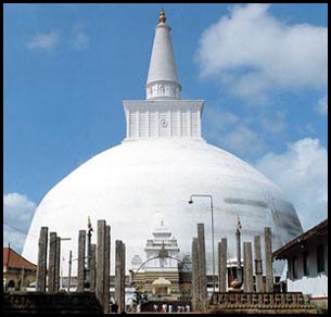
The stupa is a mound or domed structure which serves as a Buddhist reliquary, or container for relics. Stupas are a form of Mandala, or sacred form of circle in Buddhist religious traditions. The Mandala is comprised of a square within the circle. This geometric pattern is thought to symbolically or metaphysically represent the Cosmos in microcosm.


Stupas were originally simple crude piles or heaps of mud which contained artifacts of Buddha. Several thousand stupas were built after the third century, with the advent and spread of Buddhism. They eventually evolved into engineered domed structures. This evolution of structure reflected the change in the stupa from an object of memorial to one of veneration.

Most of the stupas were built as corbelled arch domes, not as true arch domes (as I discussed in an earlier blog). These corbelled arch structures require a very large amount of masonry material, resulting in very strong structures which are robust, long lived and somewhat reminiscent of the Romanesque in their extensive use of material.

Some of the great stupas famous to us today are the Great Stupa at Sanchi, India; the Dhamek Stupa in northeastern India; the Ruwanwelisaya Chedi in Sri Lanka; and the Borobudur in Indonesia: the largest Buddhist structure in the world.

The existence of such a large number of ancient stupas today is testament to the fundamental strength and stability of this domed structure. Many of these stupas have survived a long history of seismic activity and major earthquakes. This domed structure also points to the cultural acceptance and reverence for the dome in Buddhist cultures, as seen in Muslim culture relative to the mosques.
The square within the stupa (as described by four sacred gates) is an interesting manifestation of “squaring the circle” as discussed earlier on this blog. This superposition of circle and square seems a fundamental archetype of human nature, and is found across many cultures and societies. As described in An Introduction to Stupas, “"The shape of the stupa represents the Buddha, crowned and sitting in meditation posture on a lion throne. His crown is the top of the spire; his head is the square at the spire's base; his body is the vase shape; his legs are the four steps of the lower terrace; and the base is his throne." This strong cultural acceptance and reverence indicates that a domed masonry structure is readily accepted and embraced by Buddhist societies.

Tuesday, July 13, 2010

Desalination: an Idea Validated

A few entries ago, I wrote about the possibility of using a concrete sphere for desalination: or removing salt from salt water to produce fresh, potable water. I had written that a pressure of around 1,000 psi is required for forcing salt water through a semi-permeable membrane to create freshwater; furthermore, that a concrete sphere with a compressive strength of around 8,000 psi seemed like an adequate safety factor for this application; and that concrete block can be consistently, reliably and inexpensively produced with this level of strength.


If a sphere made from block with a compressive strength of 8,000 psi were sunk to a depth of 2,225 feet, the head pressure, or water pressure, at that depth would be around 1,000 psi; enough to force salt water through a semi-permeable membrane, and enough to perform reverse osmosis necessary for desalination.

Currently, desalination through reverse osmosis is problematic because of the high energy requirements necessary to force salt water through a membrane. The practice of desalination through reverse osmosis is growing rapidly around the globe, as the need for potable water increases while its availability decreases. If we can provide fresh water from salt water while avoiding the high energy requirements, this would be a giant leap forward in dealing with the problem of providing fresh, potable water. Currently, the energy needed for desalination is typically provided by burning fossil fuels to generate electricity. This is inherently problematic and ultimately not sustainable.  It also creates salt-rich effluent, which is problematic in its disposal.  Below is a picture of a desalination plant.

The key to my approach is to sink the hollow concrete sphere to the proper depth, let the “free” pressure fill a sphere with fresh water, and then to allow an inflatable bladder to float the sphere (filled with fresh water) to the surface, so no energy is required to pump fresh water up 2,225 feet. At the surface, the fresh water would be harvested and the process repeated. This would be done a large scale (with hundreds or thousands of spheres) to gain the economy of design and produce a substantial supply of fresh water.

I did some additional research to investigate whether or not my idea was valid, or would hold water, if you’ll pardon the pun. I came across an old paper titled “Laminated Concrete For Deep Ocean Construction” (authors: M.H. Karsteter, Florida State U.; W.R. Karsteter, Environmental Concrete Design Inc.; and M.E. Roms, Consultant) published for Offshore Technology Conference, 2-5 May 1988, Houston, Texas.

Here is the Abstract from this paper: “The U. S. Naval Civil Engineering Laboratory has developed formulas to predict the collapse of hollow concrete spheres or cylinders and has shown that they can remain watertight under the pressure of chemically active deep ocean seawater. This paper tabulates wall thickness, volume of concrete, weight of displaced water, and gives a concrete cost factor for several interior dimensions of one-atmosphere habitats or valve chambers for oil and gas wells, and describes a low-cost method for building submersible concrete structures by shotcrete laminating in floating formwork.”

Here is Background from this paper: “In order to determine the long-term durability of concrete in the deep ocean, the U. S. Naval Civil Engineering Laboratory immersed 18 concrete spheres in the Pacific Ocean at depths ranging from 1800 to 5000 ft. Each sphere was 66 inches in diameter with 4-inch thick walls and was designed for a working depth of about 3000 feet at 1300 psi.

The design strength of the concrete was 8000 psi but after 5 years, tests showed a 15 percent increase. This remained the same after 10 years. No visible deterioration of the concrete was observed in any of the spheres and leakage varied from 0 to only 14 gallons after 10 years.

Spheres immersed beyond the designed depth collapsed and a formula was developed to predict the wall thickness needed for concrete spheres and cylinders of various outside diameters to survive at various depths (3). The authors contemplated that in the future, methods may be developed to build massive structures on the seafloor at which time it would be desirable to have designs for negative buoyancy and deeper depths.”

This paper was done largely for and by the deep oil drilling industry. There was no intent on using this research for desalination back in 1988. Nonetheless, the results are absolutely relevant to the problem I’ve been thinking about, and I feel as though my initial insight is completely valid and justified. The authors even speak of 8,000 psi concrete. They also note that strength of concrete spheres actually increases over the first five years.

This is a significant opportunity for a large market.  Fresh water provided sustainably.

Saturday, July 10, 2010

Antoni Gaudi

“Antoni Plàcid Guillem Gaudí i Cornet” is the Catalan pronunciation of the full name of the artist and architect known to us as Antoni Gaudi (1852-1926). Gaudi is a noteworthy modernist and unique visionary who worked largely on designs gleaned from observation of nature.


His work often used parabolic, hyperbolic and catenary arches; using steel reinforced concrete.

Gaudi used masonry and tile work with an incredible facility of complexity which produced effects almost hallucinatory. He brought life to masonry.

Gaudi was deeply religious; his great unfinished work is the “Sagrada Familia” which is scheduled to open in 2026, the 100th anniversary of his death. The church is to be consecrated by Pope Benedict XVI on November 7, 2010.

Here is Gaudi speaking of Gothic:

"Gothic art is imperfect, it means to solve; it is the style of the compass, the formula of industrial repetition. Its stability is based on the permanent propping of abutments: it is a defective body that holds with support... gothic works produce maximum emotion when they are mutilated, covered with ivy and illuminated by the moon."


An interesting footnote: during the Spanish Civil War, many luminaries of the 1930’s became aware of Gaudi's work; including George Orwell. Gaudi and Orwell are two heroes of mine (one usually wants their friends to get along) but Orwell hated Gaudi’s work. C’mon George, lighten up.

Tuesday, July 6, 2010

Monolithic Domes

Monolithic Domes are a decent solution to providing a concrete dome. This involves using an inflatable bladder and spraying (or shooting) shotcrete onto the bladder in a few layers. Shotcrete is basically fluid concrete that is sprayed through a high pressure nozzle.


Monolithic domes are energy efficient, high strength, suitable for resisting hurricanes, tornadoes, fires and termites, and can be built on a fairly large scale. Monolithic domes are appropriate for some of the larger applications including municipal buildings, commercial applications and such.

Monolithic domes do require an inflatable bladder, inflation equipment, shotcrete equipment, steel "rebar" reinforcement, and some expertise in applying shotcrete.

The Monolithic Dome website provides an excellent overview of this technology, its application and its various uses and benefits. Check out their website, navigate around and investigate this interesting technology.

This is definitely not masonry, but is a useful and good application of concrete domes which certainly has an architectural niche and is worthy of consideration if anyone is considering building a concrete dome.

Monday, July 5, 2010

American Ingenuity, Dome Builders

American Ingenuity (AI) is a company that builds (or provides kits for building) concrete domes. This is a successful company with a good product, and their approach is what we’ll be looking at today.


AI uses triangular foam forms which house steel-reinforced concrete panels, which assemble into a geodesic structure. The panels are fairly large, and must be placed with heavy equipment (as opposed to simple manual installation). The Panel approach is very similar to Insulating Concrete Form (ICF) which is commonly used for more conventional construction methods.

AI has been around since 1976, and has a long and successful history of providing affordable, high performance, energy efficient structures based on geodesic geometry. Their website states “In over 30 years American Ingenuity's domes have survived all major USA hurricanes, tornados and a Hawaiian earthquake, with no structural damage! If more homeowners and government officials in Haiti, Africa, the Pacific Fire Rim, USA earthquake areas of western & middle America, built American Ingenuity Domes, there would be less deaths and home destructions.”

AI provides a good solution for constructing geodesic domes. For a more complete summary of AI’s products, just navigate through their website. They have a very useful website.

The approach I’ve developed differs from AI’s in that mine is a true masonry system. That is, masonry units are kept small enough to be handled by an individual mason. I also use a unique interlocking feature which their system lacks. My interlock allows for the incorporation of conjugate shearing, as described several times in this blog.

The masonry system I’ve developed can also be used to build vaulted arches, straight walls, square corners, arches at right angles, and arches merging into larger domes. AI’s system exhibits nice design flexibility also, although our approaches are different. AI’s requires more custom forms and carpentry, whereas my approach simply uses a couple of different shaped masonry units to build arches, cylinders and straight walls.

Finally, the masonry system I’ve developed can be provided at a lower cost due to the high efficiency, high strength and low cost of manufactured block provided by today’s block manufacturers.

If anyone is looking for a good construction solution, take a look at American Ingenuity. They have a very good system.

Sunday, July 4, 2010

Evaluating a masonry dome

A friend of mine, Dick Fischbeck, recently shared an article with me about concrete domes built at Yerba Buena Center for the Arts in San Francisco, California. Mr. Fischbeck is a follower of R. Buckminster Fuller, and believes –as Fuller did- that weight is an important criterion for evaluating a building. As I discussed earlier in this blog, if a building weighs too much, it is fundamentally flawed, according to Fuller and his followers. So Mr. Fischbeck sent me this article, writing “here’s a bad idea for you!”

I read this article and was quite intrigued. I had to agree with Dick, that this seemed like a bad idea, although I suspect I have different reasons for thinking so. This is an interesting example which shows many of the advantages of the triangular interlocking masonry system which I’ve been describing on this blog, versus conventional masonry assembled with rectangular bricks and blocks.

At the risk of upsetting this large team of engineers, architects, artists, donors, sponsors, volunteers and anyone else involved in this project, I will now offer my informed critique of this structure. It is my intention to show that a better system is available for masonry construction of domes and spherical sections. Given that Mark Sinclair, a principal at Degenkolb Engineering, which donated expertise and staff time to this project, is quoted as stating "Part of the reason I'm excited is that with something like this, you see how it could be applied (economically) to homes and small commercial buildings," I am gently trying to point out that there is a much better way to build masonry domes than what was done here, and to apply this improved masonry method to the economical construction of homes and small commercial buildings.

First, if we look at the assembled structure built at Yerba Buena, the profile of the dome structure is accentuated by undulations and sharp changes in the radial design it attempts to describe. These undulations create undue and unwanted focal points for stress. At these locations, the stresses become focused and serve as points where failure is more likely to occur. A more stable design is provided if the structure is kept truly radial or catenary, such that there is no focal point for stress.


Michael Ramage, an engineer who attended MIT and is currently teaching at Cambridge University in England, designed this dome system at Yerba Buena. Dr. Ramage is quoted as saying "Vagaries of construction are to be accepted ... We let the structural forces dictate what the forms want to be," in explaining the undulations found in this dome system. To me, these “vagaries” are to be minimized, avoided and are not acceptable. To me, they visually detract from the form, and from an engineering standpoint provide focal areas of stress which weaken the structure. To me, the architect, designer and builder should dictate what the form is, not the vagaries of construction. 


Second, a rectangular brick or block is not the ideal unit shape for assembling a dome structure. As discussed earlier in this blog, a triangular block is inherently disposed to conjugate shearing along control joints, so that stress is allowed to be relieved through strain (movement) in a controlled manner; the structure is “pre-fractured” and is thus less likely to suffer a fracture by nature of its being pre-broken.

A rectangular block or brick simply cannot be assembled into a sphere (or dome) without the creation of gaps or spaces between bricks, unless the bricks are custom cut and fitted to their specific location. Conversely, triangular blocks can be assembled into a number of polyhedral arrangements, without creating gaps or spaces between bricks. These triangular unit shapes are interchangeable and do not have to be custom cut or placed at specific locations within a dome or sphere.


If a very large dome is assembled, and mortar is used between bricks, then the effect of gaps or spaces between bricks is minimized. One obvious example of a well-executed dome built with rectangular bricks is the Brunelleschi’s Duomo, which also utilized a herringbone pattern for bricklaying. On a smaller scale (smaller domes, like the Yerba Buena domes), these gaps and spaces between bricks are noticeable, and have an effect on both the visual appearance of a structure and its engineering performance. 

The domes assembled at Yerba Buena were done with two concentric shells of brick; one interior and one exterior. Between these shells, a geotextile fabric was included as a tensile element to help provide some tensile reinforcement to the overall structure. To me, this use of geotextile fabric appeared somewhat sloppy, wasteful and inelegant.

The masonry system I have developed and am attempting to describe on this blog also allows for concentric shells to be assembled, if so desired. Also, the interlocking “DIMP” design allows for a tensile element to be incorporated into the structure, in a more efficient and simple system which involves weaving this tensile element into the blocks as they are assembled. This incorporation of tensile elements is done so that the tensile elements are placed at the conjugate shear planes within the structure, resulting in a stronger, tougher system which utilizes active control joints, allowing for stress (applied force) to be relieved via strain (movement).

This notion of allowing stress to be relieved by strain figures critically into another aspect of evaluating masonry domes regarding seismic stresses. In the Yerba Buena structure, the architects, engineers and designers had to design the structure so that it was suitable for earthquakes which are more likely to occur at this location. Their design dealt with this engineering challenge by providing a rigid dome, which will move as a whole, atop a base isolation system. If the ground were to move underneath the dome, the whole dome is free to move in its entirety; like an upside down bowl placed atop ball bearings. This engineering solution requires an expensive and extensive base isolation mechanism which the structure sits on top of. In contrast, the interlocking triangular block system I’ve been describing in this blog relies on the ability to deform (strain) under seismic forces (stress). This is possible through both the interlocking feature of the block and tensile elements (steel cable, carbon fiber, etc.) woven into the block as they are assembled. Each tensile element is anchored at the base of the dome, and fitted with a spring which dampens the stresses and add to the dynamic flexibility of the dome. Thus the Yerba Buena domes and the domes I’ve developed have fundamentally different approaches to dealing with seismic stresses. They rely on the entire dome being able to move relative to the ground, and my design relies on the ability of the structure to strain along control joints, via conjugate shearing. The design I’ve developed is further advantageous because a dome thus constructed can sit atop vertical walls, and is still free to move; the Yerba Buena dome cannot be built atop vertical walls, unless the entire structure (including vertical walls) is allowed to move via a base isolation system. Again, this requires more extensive and expensive engineering features.

The Yerba Buena dome used lightweight bricks for their construction. This seemed to me an unnecessary feature. With concrete bricks, any reduction in weight is also accompanied by a reduction in strength. One of the fundamental features of a masonry dome is its high compressive strength: there is really no reason to use a lightweight block, unless one is a strict adherent to the principals of Bucky Fuller. It seems to me that this structure was made less strong by using lightweight bricks. The only real advantage to lightweight bricks is that they serve as better thermal insulators. However, this occurs at the loss of thermal mass to the structure, which is a beneficial aspect of masonry construction. I believe (as do others) that a more thermally efficient structure is provided by incorporating a high thermal mass, and simply insulating the outside of the structure so as to maximize the thermal mass benefits.

It should be noted that lightweight masonry units are in fact advantageous for high temperature refractory applications, where thermal insulation benefits outweigh the thermal mass benefits at high operating temperatures, such as in a kiln or furnace. The kilns and furnaces I’ve built using my masonry system did incorporate liquid foam insulation into the cast bricks, to provide a lightweight insulating brick.

If a dome were built with standard manufactured rectangular concrete block, the dome would have the block oriented such that the weak axis of compressive strength is facing the outside, or radial, direction (the weak axis is normal to the axis of compression as the block are made). The triangular concrete block which I’ve developed have the high strength axis (direction of concrete compaction and consolidation during manufacture) facing the outside. This provides a much stronger structure.

This wraps up my evaluation of the Yerba Buena dome system. It is my hope that anyone reading this critique can do so in the constructive manner in which it was intended. I am certainly very happy to see others attempting to build concrete domes today, and to aspire to creative solutions to some challenging engineering problems. If anyone wants to try and build a better concrete masonry dome, please contact me; I may be able to help. I am willing to allow use of my patented systems at no cost for interesting and worthy projects such as this.

Construction is a conservative industry. Within construction, the field of masonry is even more conservative. I hope to advance the state of masonry today, through a thoughtful approach, using good design and appropriate use of materials.